Method and device for supply of a dialysis unit with dialysis fluid

a technology of dialysis unit and dialysing fluid, which is applied in the direction of instruments, multi-stage water/sewage treatment, separation processes, etc., can solve the problems of incorrect disposal of packaging materials, inability to match the needs of individual patients, and easy handling of dialysing fluid concentrates supplied from a central source, so as to increase the overall level of dialysance, the effect of increasing the flow rate of dialysing fluid and increasing the dialysing fluid flow ra

Active Publication Date: 2013-07-30
FRESENIUS MEDICAL CARE DEUTSCHLAND GMBH
View PDF7 Cites 14 Cited by
  • Summary
  • Abstract
  • Description
  • Claims
  • Application Information

AI Technical Summary

Benefits of technology

[0011]The procedure or the equipment in accordance with the invention renders it possible to adjust the rate of flow of the dialysing fluid to a level which lies above the minimum rate necessary for the treatment so that the overall level of dialysance is increased.
[0012]In a conventional dialysis treatment, the doctor prescribes a particular dose level of dialysis by specifying appropriate rates of flow for the blood and the dialysing fluid for a particular type of dialyser as well as an appropriate treatment time. In practice, the quantities of concentrates made available are determined in such a manner that in general they are adequate for treatments with different dialysing fluid rates. Consequently, in practice the concentrate is not completely used up. The procedure or the equipment in accordance with the invention makes use of the residual amount of concentrate to permit a higher rate of flow of the dialysing fluid. This has the advantage that when a higher rate of flow is used, the dialysing dose rate is increased which has a beneficial effect upon the treatment. For example, the efficiency of a hollow fiber dialyser increases with increasing rates of flow of dialysing fluids up to an asymptotic limiting value.
[0014]The pre-set residual quantity of concentrate can then be used to prepare the dialysing fluid in a quantity necessary for an appropriate extension of the treatment, thus ensuring that the effective length of treatment is attained.

Problems solved by technology

Dialysing fluid concentrates supplied from a central source are easy to handle but have the disadvantage that they cannot be matched to the needs of an individual patient.
However, correct disposal of the packaging materials by granulation or combustion is only possible after the canister or bag has been completely emptied with the consequence that any residual material left in the canister or in the bag after treatment must be discarded.
Furthermore, the disposal of the excess quantity of concentrate to waste constitutes a material loss.

Method used


Image

  • Method and device for supply of a dialysis unit with dialysis fluid
  • Method and device for supply of a dialysis unit with dialysis fluid
  • Method and device for supply of a dialysis unit with dialysis fluid

Examples


Embodiment Construction

[0024]In the following, two embodiment examples of the procedure and the equipment in accordance with the invention are explained in more detail by reference to the drawings.

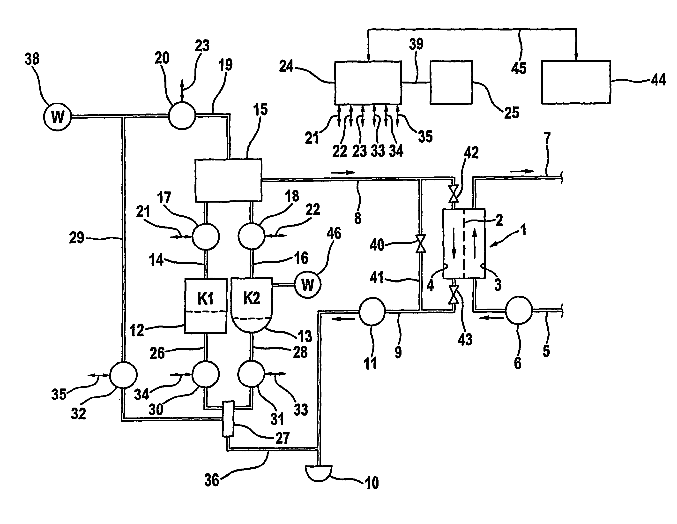
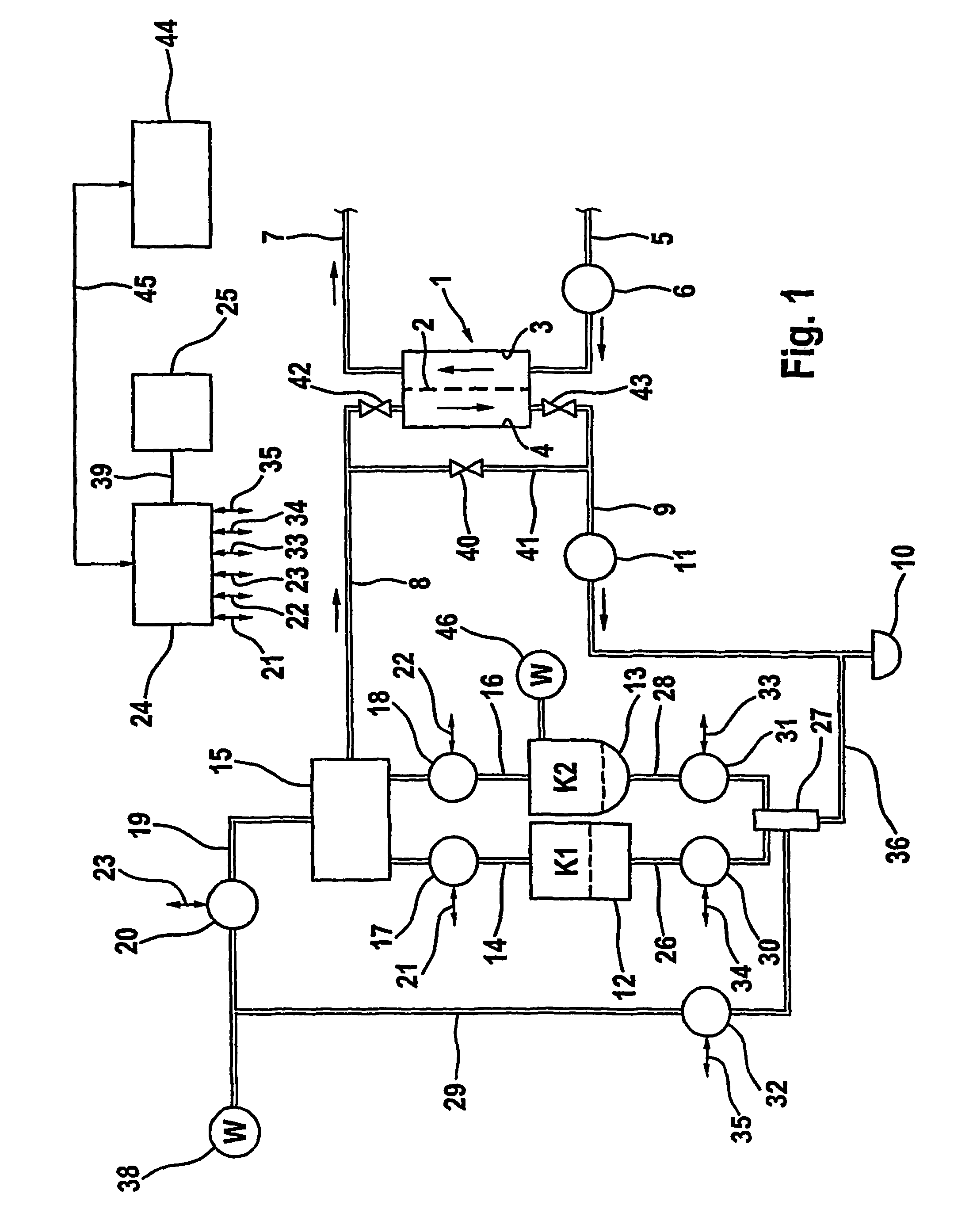
[0025]The hemodialysis equipment exhibits a dialyser 1 which is divided into a blood chamber 3 and a dialysing fluid chamber 4 by a semi-permeable membrane 2. The inlet to the blood chamber 3 is connected to one end of blood supply pipe 5 in line with a blood pump 6 while the outlet of the blood chamber is connected to the end of a blood return pipe 7. A dialysing fluid supply pipe 8 leads to the inlet of the dialysing fluid chamber 4 and from the outlet of the dialysing fluid chamber a dialysing fluid outflow pipe 9 leads to a waste discharge 10. A dialysing fluid pump 11 is in line with the dialysing fluid outflow pipe 9. During the course of the dialysis treatment, the patient's blood flows through the blood chamber 3 of the dialyser 1 while a counterflow of dialysing fluid passes through the dialysing fluid ...


PUM

PropertyMeasurementUnit
flow rate Qdbaaaaaaaaaa
residual volumeaaaaaaaaaa
fluid flow rate Qdbaaaaaaaaaa

Abstract

A method and a device for supply of a dialyser in a dialysis unit with dialysis fluid is disclosed. At least one dialysis fluid concentrate is mixed with water to produce the dialysis fluid. The dialysis fluid concentrate is prepared in a reservoir unit in a given amount. A control and arithmetic unit calculates the dialysis fluid rate (Qd) such that, after a given treatment time (TB) has passed, a given residual amount of dialysis fluid concentrate or no residual amount remains in the reservoir unit. It is preferable to empty the reservoir unit by the end of treatment.

Description

FIELD OF THE INVENTION[0001]The invention relates to a procedure and equipment for supplying a dialysis unit with dialysing fluid.BACKGROUND OF THE INVENTION[0002]It is customary today to use pre-prepared dialysing fluid concentrates to produce dialysing fluid for hemodialysis units, whereby the concentrate is diluted with water in the dialysis unit. In dialysis centers, dialysing fluid concentrates are made available either as pre-prepared products in canisters or bags or they are delivered via a ring piping system from a central tank.[0003]The dialysing fluid is fed to the dialyser of the dialysis unit, which is divided by a semi-permeable membrane into a dialysing fluid chamber and a blood chamber. While the patient's blood flows continuously through the blood chamber, the dialysing fluid flows continuously as a counter-current through the dialysing fluid chamber.[0004]Dialysing fluid concentrates supplied from a central source are easy to handle but have the disadvantage that th...

Claims


Application Information

Patent Timeline
Patent Type & Authority Patents(United States)
IPC IPC(8): B01D63/00C02F1/44A61M1/16
CPCA61M1/16A61M1/14A61M1/1613A61M1/1656A61M2205/3334A61M2205/50A61M1/1601A61M1/1666Y10T137/0318Y10T137/2557Y10T137/86389
Inventor REMKES, GERARDWIESEN, GERHARD
Owner FRESENIUS MEDICAL CARE DEUTSCHLAND GMBH
Why Eureka
Try Eureka