Cerebrospinal fluid evaluation system having thermal flow and flow rate measurement pad using a plurality of control sensors

a technology of control sensors and evaluation systems, which is applied in the field of cerebrospinal fluid shunts, can solve the problems of failure to teach or suggest an apparatus/method for quantifying the flow of fluid through the shunt, variations in the thermistor signal, and the apparatus/method disclosed in the apparatus/method suffers

Active Publication Date: 2013-10-08
NEURO DIAGNOSTIC DEVICES
View PDF16 Cites 5 Cited by
  • Summary
  • Abstract
  • Description
  • Claims
  • Application Information

AI Technical Summary

Problems solved by technology

However, among other things, the apparatus and method disclosed therein fails to teach or suggest an apparatus / method for quantifying the flow of the fluid through the shunt.
However, the apparatus / method disclosed therein suffers from, among other things, variations in thermistor signal due to environmental changes.

Method used


Image

  • Cerebrospinal fluid evaluation system having thermal flow and flow rate measurement pad using a plurality of control sensors
  • Cerebrospinal fluid evaluation system having thermal flow and flow rate measurement pad using a plurality of control sensors
  • Cerebrospinal fluid evaluation system having thermal flow and flow rate measurement pad using a plurality of control sensors

Examples


Embodiment Construction

[0033]This application incorporates by reference the disclosure of application Ser. No. 12 / 055,990, filed on Mar. 26, 2008 entitled CEREBRAL SPINAL FLUID EVALUATION SYSTEMS. The invention of the present application includes further improvements of the inventions disclosed in U.S. Ser. No. 12 / 055,990.

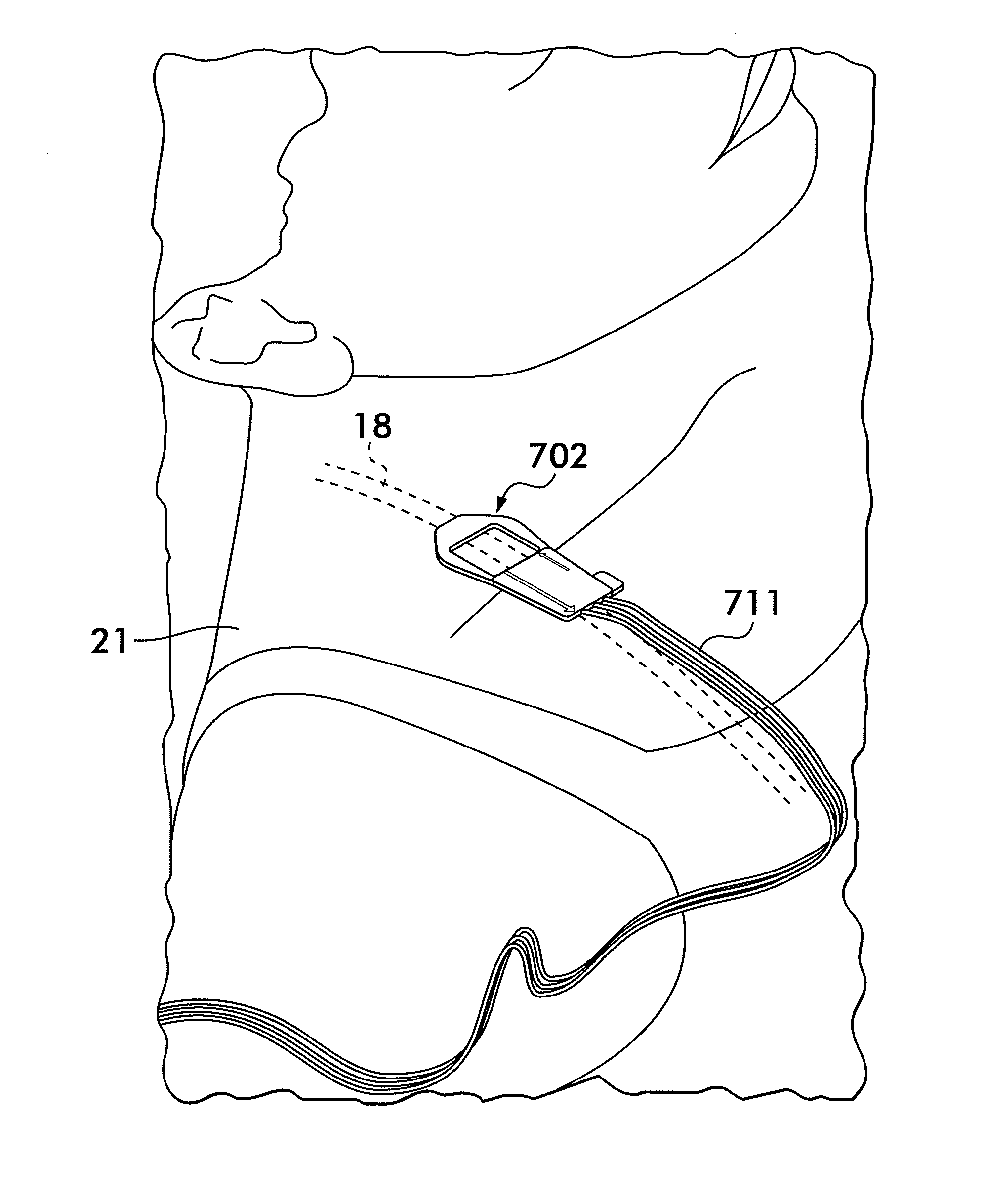
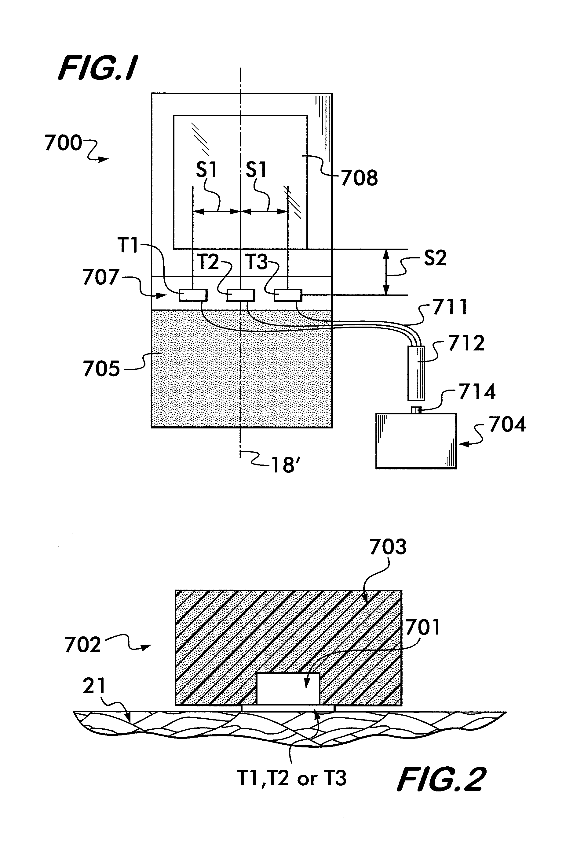
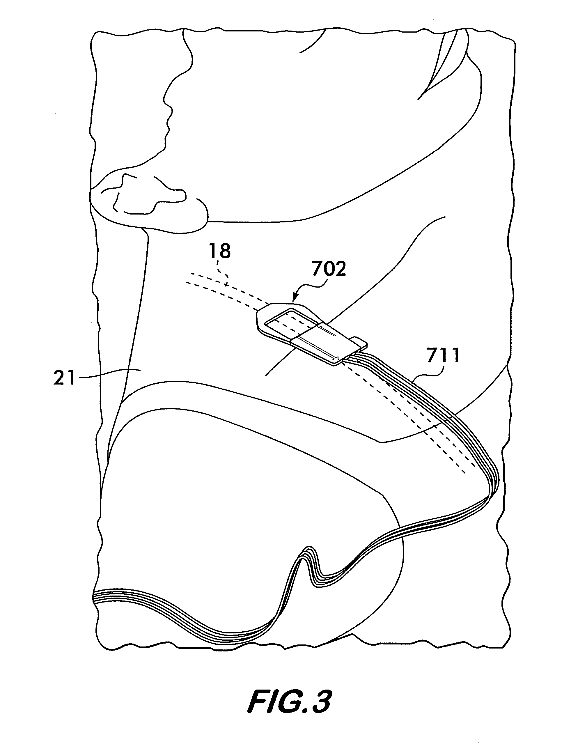
[0034]Referring now to FIG. 1, there is shown a functional diagram of the system and method of the present invention 700. In particular, the invention 700 comprises a thermal flow measurement pad 702 which is in electrical communication with a CSF analyzer 704, also known as a sensor processing device (e.g., a processor with I / O). As will be discussed in detail later, the measurement pad 702 comprises a plurality of sensors, such as thermistors, which are maintained in the correct relative geometries by the measurement pad 702. The analyzer 704 also provides the sensor excitation. The measurement pad 702 improves the performance of methods for thermal measurement of CSF flow in implanted...


PUM


Abstract

A method and device for testing for the presence, absence and / or rate of flow in a shunt tubing implanted under the skin by using a measurement pad having a plurality of temperature sensors, one of which is aligned with the shunt and the other sensors being symmetrically displaced on either side of the first temperature sensor in a direction transverse to the shunt tubing. These “outer” temperature sensors act as control temperature sensors. A temperature source, e.g., a cooling agent, positioned within an insulated enclosure, is then applied at a predetermined location on the measurement pad that is insulated from the temperature sensors. The movement of this temperature “pulse” is detected by the shunt-aligned temperature sensor via the shunt tubing as the CSF carries the temperature pulse while the control sensors detect the pulse via convection through the skin. The temperature data from these sensors are provided to a CSF analyzer that determines a CSF shunt flow status or flow rate.

Description

CROSS-REFERENCE TO RELATED APPLICATIONS[0001]This application is a national stage application that claims the benefit under 35 U.S.C. §371 of International Application No. PCT / US2009 / 039146 filed on Apr. 1, 2009, which in turn takes its priority from U.S. Provisional Application No. 61 / 042,496 filed on Apr. 4, 2008 and also claims the benefit under 35 U.S.C. §120 and 37 CFR §1.78(a)(2)(ii) of U.S. application Ser. No. 12 / 055,990 filed on Mar. 26, 2008, which in turn claims the benefit of U.S. Provisional Application No. 60 / 989,284 filed on Nov. 20, 2007, and of U.S. Provisional Application No. 60 / 941,827 filed on Jun. 4, 2007, and of U.S. Provisional Application No. 60 / 939,205 filed on May 21, 2007, and of U.S. Provisional Application No. 60 / 911,687 filed on Apr. 13, 2007, and all of whose entire disclosures are incorporated by reference herein.BACKGROUND OF THE INVENTION[0002]1. Field of Invention[0003]The present invention generally relates to cerebrospinal fluid shunts and, more ...

Claims


Application Information

Patent Timeline
Patent Type & Authority Patents(United States)
IPC IPC(8): A61B5/03G01F1/684
CPCA61M27/006A61B5/028
Inventor FRITZ, FREDERICK J.SWOBODA, MAREK
Owner NEURO DIAGNOSTIC DEVICES
Why Eureka
Try Eureka