Optical sheet with unit prisms including unit prism groups

a technology of optical sheets and prism groups, applied in the field of sheets, can solve the problems of not being able to solve the problems fully, not being able to produce optical sheets with unit prisms, and not being able to achieve optical sheets in the practicability field, so as to achieve the effect of overcoming or reducing the number of sheets

Active Publication Date: 2014-12-02
DAI NIPPON PRINTING CO LTD
View PDF18 Cites 6 Cited by
  • Summary
  • Abstract
  • Description
  • Claims
  • Application Information

AI Technical Summary

Benefits of technology

[0015]The present invention has been made in view of the above situation. It is therefore an object of the present invention to provide an optical sheet having unit prisms, which can alleviate or overcome the problems which have been encountered when a conventional optical sheet is superimposed on another member. It is another object of the present invention to provide a surface light source device, a transmission type display device and a light emitting device each having the optical sheet. It is yet another object of the present invention to provide a mold for molding the optical sheet, and a method for producing the mold.

Problems solved by technology

Various problems may arise when two optical sheets are superimposed on each other, or when the light exit side surface (light outgoing side surface) of a surface light source device and the light entrance side surface (light incident side surface) of a transmission type display unit are superimposed on each other and optically unified.
It has been found through the present inventors' studies that such problems arise not only when the surfaces of two members make plane contact with each other but also when the unit prisms of the above described optical sheet, having the ridge lines, make contact with another member.
However, in view of influence on the quality of display images and also of the production cost, it is not possible in actual mass production to produce an optical sheet with unit prisms having largely varying heights.
Thus, the unit prisms having moderately undulating curved ridge lines make contact with another member in a larger area than has been expected, making it impossible to fully solve the problems.
For these reasons, it is not practically possible for the optical sheet of JP 8-304608A to substantially solve the above problems.
Thus, because of constraint by adjacent unit prisms, the degree of horizontal undulation of each unit prism cannot be made sufficiently large.
Furthermore, the optical sheet of U.S. Pat. No. 7,072,092 is not effective to solve the problems of “direct passage of light” and “wet-out”.
For these reasons, it is not practically possible for the optical sheet of U.S. Pat. No. 7,072,092 to substantially solve the above problems.
The production of such a mold is very difficult and incurs a considerably increased production cost.
This leads to a considerably high production cost of the optical sheet of JP 2008-544303T compared to an optical sheet having a linear array of linearly-extending unit prisms.
As described hereinabove, the problems that arise when superimposing an optical sheet having unit prisms on another member have not been fully solved as yet.
The above-described problems with a surface light source device or a display device may likewise arise in such a light emitting device when the device includes a plurality of optical sheets or when an optical sheet of the device makes contact with a member adjacent to the device.
Nowadays, when environmental issues are attracting continued attention, enhancement of the energy efficiency in a surface light source device is an important problem.

Method used


Image

  • Optical sheet with unit prisms including unit prism groups
  • Optical sheet with unit prisms including unit prism groups
  • Optical sheet with unit prisms including unit prism groups

Examples


Embodiment Construction

[0049]Preferred embodiments of the present invention will now be described with reference to the drawings. In the drawings, for the sake of illustration and easier understanding, scales, horizontal to vertical dimensional ratios, etc. are exaggeratingly modified from those of the real things.

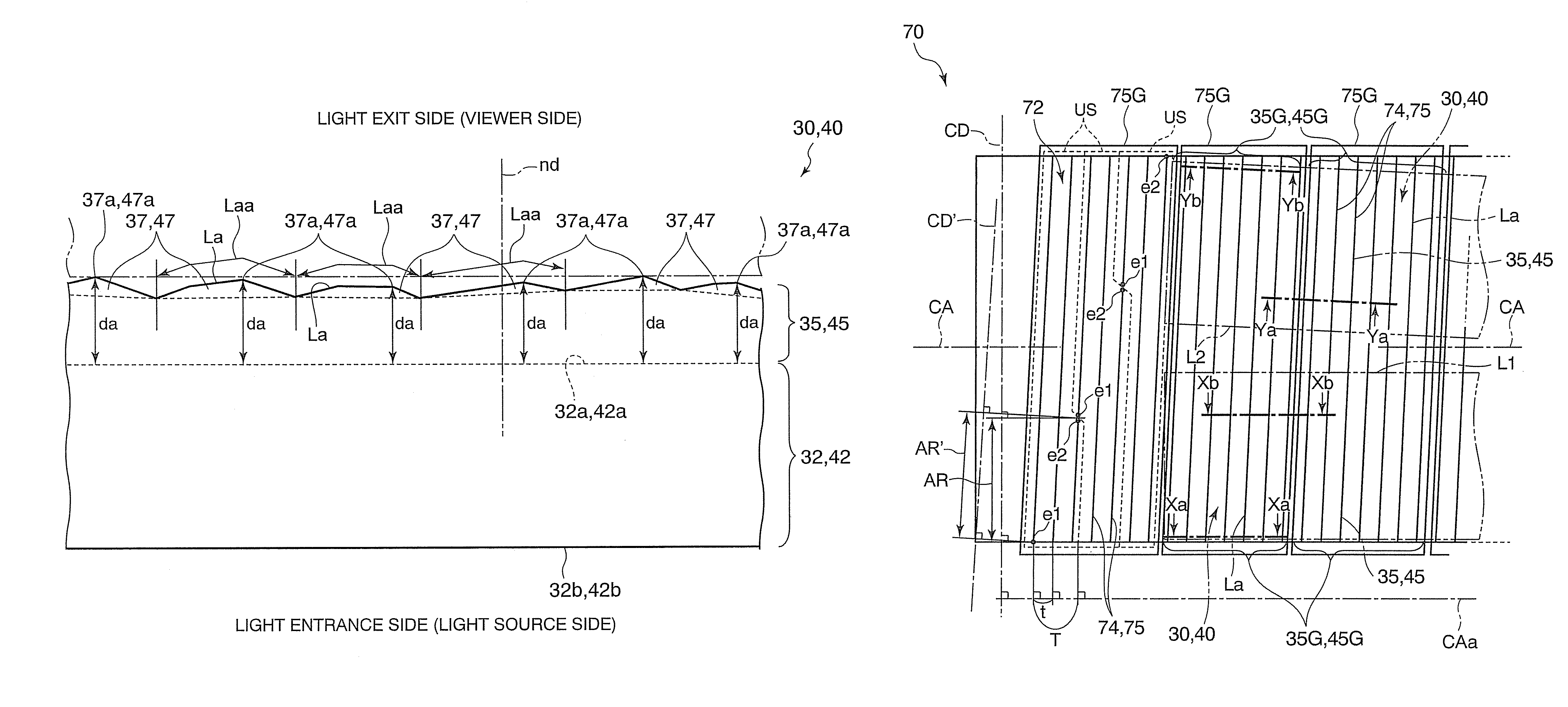
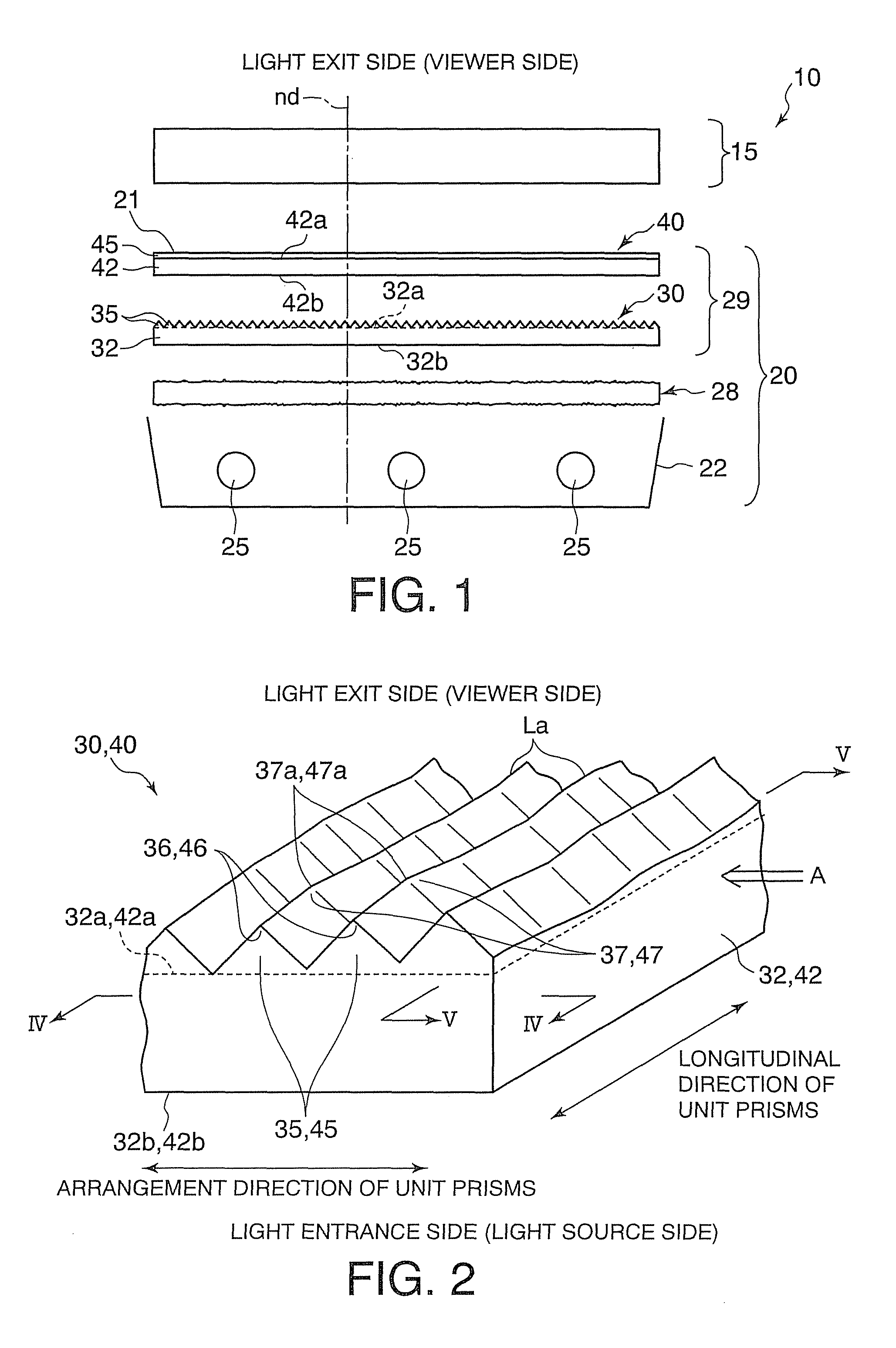
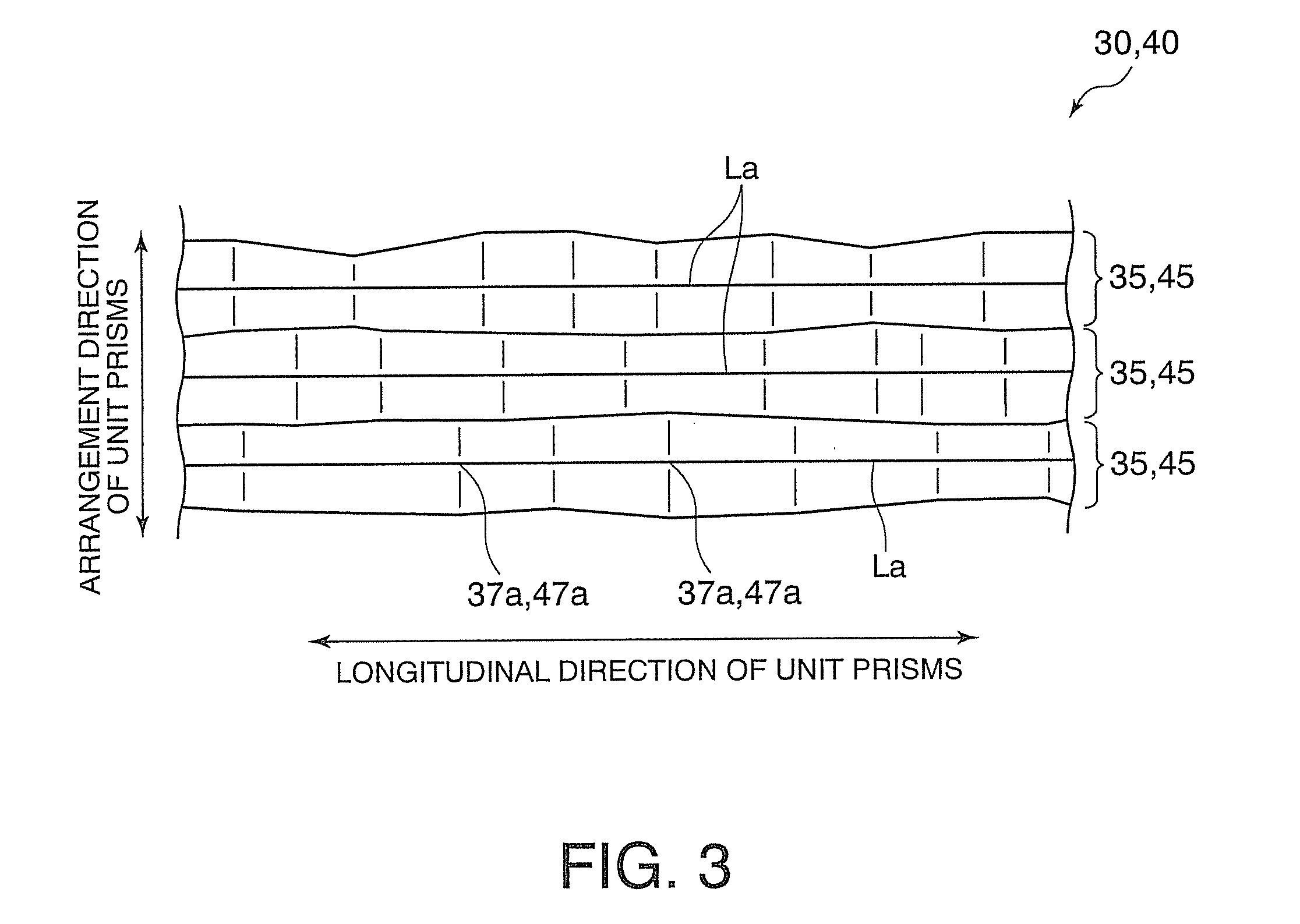
[0050]FIGS. 1 through 12 are diagrams illustrating an embodiment of the present invention. Of these, FIG. 1 is a schematic cross-sectional view of a transmission type display device and a surface light source device; FIG. 2 is a perspective view of an optical sheet; FIG. 3 is a top view of the optical sheet; FIG. 4 is a cross-sectional view taken along the line IV-IV of FIG. 2; and FIG. 5 is a cross-sectional view takes along the line V-V of FIG. 2.

[0051]The transmission type display device 10 shown in FIG. 1 includes a transmission type display unit 15 and a surface light source device 20, disposed on the back side (the opposite side from a viewer or the light entrance side) of the transmission...


PUM

PropertyMeasurementUnit
beam transmittanceaaaaaaaaaa
total light beam transmittanceaaaaaaaaaa
heights daaaaaaaaaaa

Abstract

An optical sheet includes a sheet-like body portion, and unit prisms arranged on one surface of the body portion. Each unit prism extends linearly in a direction intersecting the arrangement direction. Each unit prism, when viewed in a direction parallel to the arrangement direction of the unit prisms, has an uneven polygonal-line-shaped contour and, with reference to raised portions defined by the polygonal-line-shaped contour of each unit prism, the distance between a top of each raised portion, a farthest point from the body portion in the raised portion, and the body portion in the normal direction of the body portion is not constant. The optical sheet can prevent significant problems when it is superimposed on another member.

Description

BACKGROUND OF THE INVENTION[0001]1. Field of the Invention[0002]The present invention relates to a sheet for changing the travel direction of light, and more particularly to an optical sheet which can prevent cause significant problems when it is superimposed on another member. The present invention also relates to a surface light source device, a transmission type display device and a light emitting device each having such a useful optical sheet. Further, the present invention relates to a mold for molding such a useful optical sheet and to a method for producing the mold.[0003]2. Description of Related Art[0004]A surface light source device which, together with a transmission type display unit (e.g. liquid crystal panel), constitutes a transmission type display device, includes a light source and a number of optical sheets (optical films) for changing the travel direction of light from the light source, as disclosed e.g. in JP 8-304608A, U.S. Pat. No. 7,072,092 and JP 2008-544303T...

Claims


Application Information

Patent Timeline
Patent Type & Authority Patents(United States)
IPC IPC(8): G02B5/04G02F1/1335F21V8/00F21V7/04F21Y101/00
CPCG02B6/0053G02F2001/133607G02B6/0078G02F1/133606G02B5/045G02F1/133611G02B6/0065Y10T83/05Y10T82/10B23B1/00B23B2270/54B29C59/002G02F1/133607B29C59/043B32B1/00B29D11/00798
Inventor KOJIMA, HIROSHIGOISHIHARA, SATOSHIMAENISHI, SATOKO
Owner DAI NIPPON PRINTING CO LTD
Why Eureka
Try Eureka