LED-illuminated sign

a technology of led lights and led drivers, applied in the field of led lights, can solve the problems of difficult to keep electronic led drivers in water/air tight locations, difficult to protect electronic led drivers, and difficult to meet the requirements of outdoor applications using leds as light sources. , to achieve the effect of excellent heat dissipation, excellent protection, and good protection of electronic led drivers

Active Publication Date: 2015-08-11
IDEAL IND LIGHTING LLC
View PDF15 Cites 0 Cited by
  • Summary
  • Abstract
  • Description
  • Claims
  • Application Information

AI Technical Summary

Benefits of technology

[0007]Another object of the invention is to provide an improved outdoor LED-illuminated sign with excellent protection of the electronic LED drivers needed for such products.
[0008]Still another object of the invention is to provide an improved LED-illuminated sign with both good protection of electronic LED drivers and excellent heat dissipation.
[0014]In preferred embodiments, each LED emitter includes an LED module and a lens thereover configured to spread the light from the LED module, thereby to facilitate substantially uniform illumination of the shell.

Problems solved by technology

High-luminance light fixtures using LEDs as light source for outdoor applications present particularly challenging problems.
High costs due to high complexity becomes a particularly difficult problem when high luminance, reliability, and durability are essential to product success.
Keeping electronic LED drivers in a water / air-tight location may also be problematic, particularly when the light fixtures are constantly exposed to the elements and many LEDs are used.
Dealing with heat dissipation requirements is still another problem area for high-luminance LED light fixtures.
Heat dissipation is difficult in part because high-luminance LED light fixtures typically have many LEDs.
Complex structures for module mounting and heat dissipation have sometimes been deemed necessary, and all of this adds to complexity and cost.

Method used


Image

  • LED-illuminated sign
  • LED-illuminated sign
  • LED-illuminated sign

Examples


Embodiment Construction

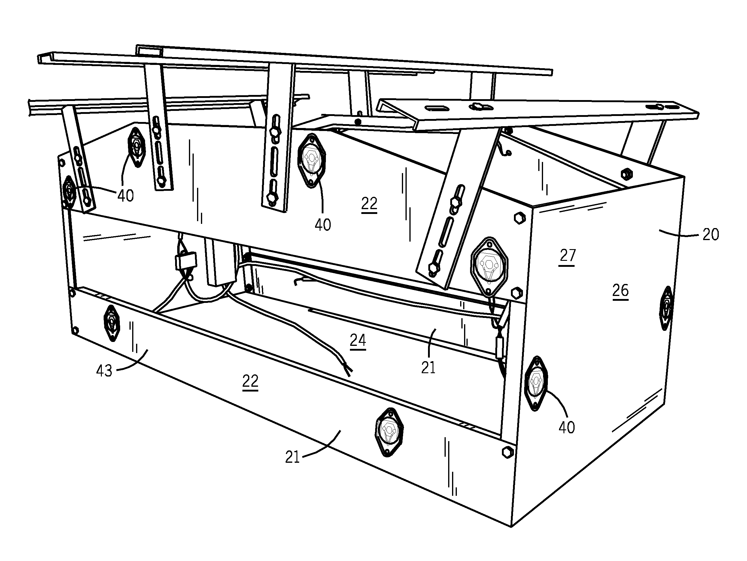
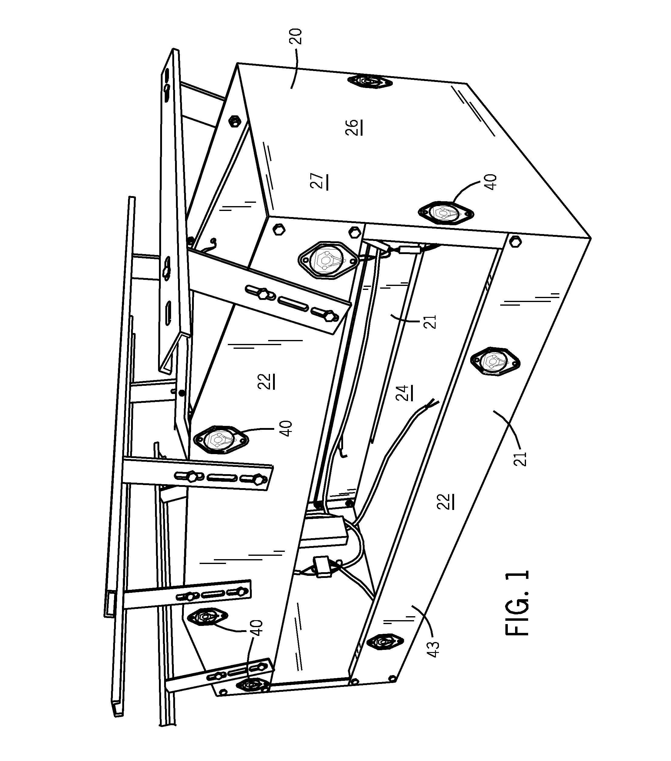
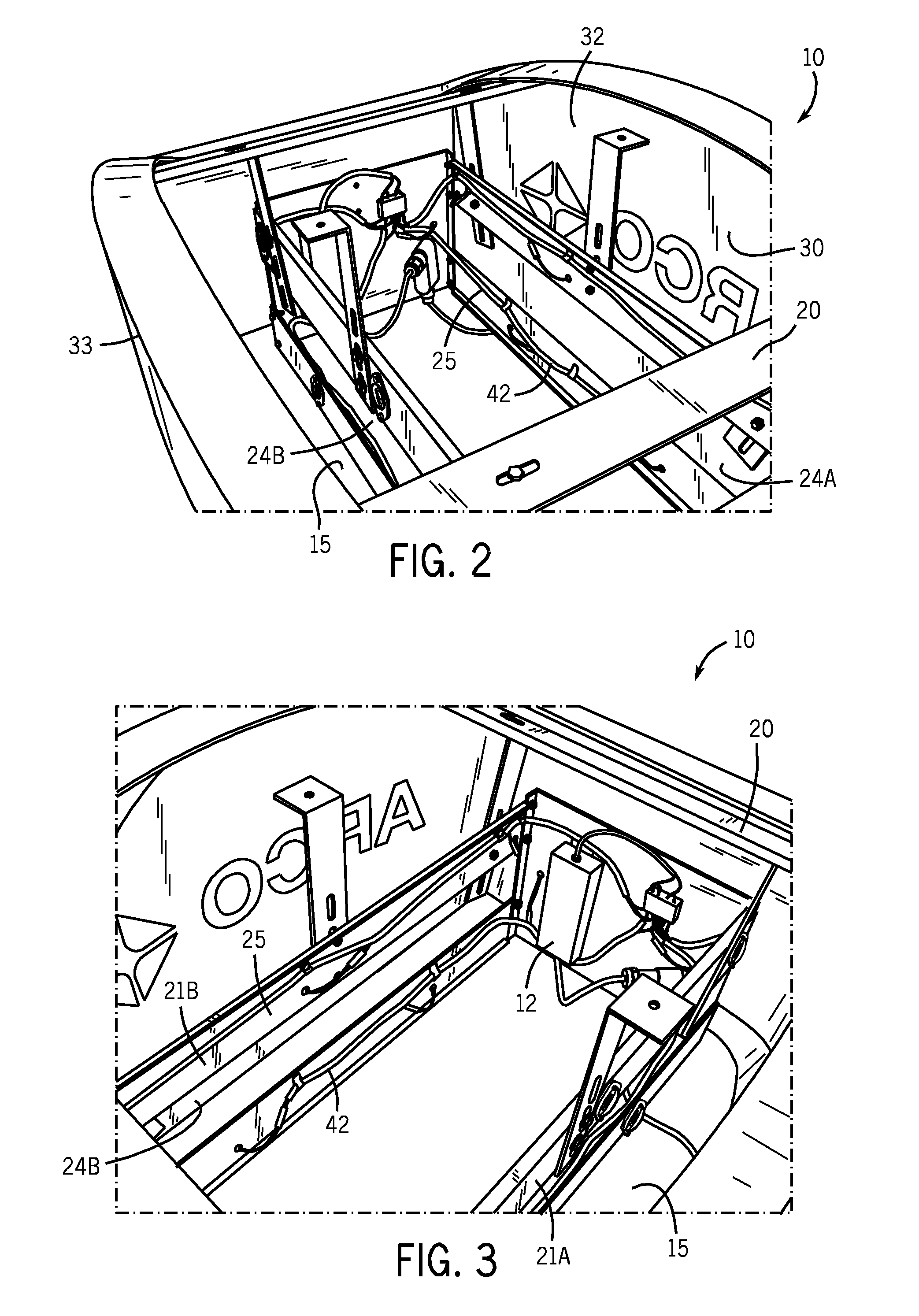
[0032]FIGS. 1-10 illustrate a preferred LED-illuminated sign 10. As best seen in FIGS. 1-5, inventive LED-illuminated sign structure 10 includes a frame 20, an outer shell 30 and a plurality of separate LED emitters 40. Frame 20 may be for securement atop a service-station fuel-pump unit (not shown) and may be secured with respect to the upper portion of the pump unit. FIGS. 1-3 best show that frame 20 includes two opposite main support panels 21 each of which has a substantially upright outward surface 22 and shell-supporting members 23.

[0033]FIGS. 2-5 illustrate that outer shell 30 is secured to shell-supporting members 23 of frame 20 and has a pair of opposite translucent sidewalls 31 with an inner surface 32 and an outer surface 33. As seen in FIGS. 2 and 3, shell 30 and shell-supporting members 23 are configured and arranged such that each translucent sidewall 31 extends along and is spaced from outward surface 22 of a respective one of main support panels 21. Outer shell 30 fu...


PUM

PropertyMeasurementUnit
translucentaaaaaaaaaa
heataaaaaaaaaa
luminanceaaaaaaaaaa

Abstract

The inventive LED-illuminated sign structure includes a frame, an outer shell and a plurality of separate LED emitters. The frame includes two opposite main support panels each having an upright outward surface, and shell-supporting members. The outer shell has a pair of opposite translucent sidewalls each extending along and is spaced from the respective outward surface. The LED emitters are spaced on each outward surface such that the translucent sidewalls are illuminated substantially entirely. The frame defines an open region for passing reflected light within the frame structure to and through the opposite translucent sidewall. The LED illuminator includes an LED emitter on a mounting surface, a one-piece lens member over the LED emitter and including a lens portion and a flange portion, and a gasket between the flange portion and the mounting surface. The lens member has a restraining ridge positioned to press the LED-emitter wires and the gasket against the mounting surface such that the wire portions between the ridge and the LED emitter remain in substantially fixed position regardless of wire movement beyond the restraining ridge.

Description

FIELD OF THE INVENTION[0001]This invention relates to light fixtures. More particularly, this invention relates to such light fixtures which utilize LEDs as light source for internal illumination of signs and the like.BACKGROUND OF THE INVENTION[0002]In recent years, the use of light-emitting diodes (LEDs) for various common lighting purposes has increased, and this trend has accelerated as advances have been made in LEDs and in LED-array bearing devices, often referred to as “LED modules.” Indeed, lighting applications which have been served by fixtures using high-intensity discharge (HID) lamps, fluorescent lamps and other light sources are now increasingly beginning to be served by LEDs. Such lighting applications include, among a good many others, roadway lighting, parking lot lighting, sign illumination and many other applications. Creative work continues in the field of using LEDs for light fixtures in various applications. It is the latter field to which this invention relate...

Claims


Application Information

Patent Timeline
Patent Type & Authority Patents(United States)
IPC IPC(8): G09F13/04
CPCG09F13/0409G09F13/0413
Inventor MILETICH, DONSTANLEY, JOHN
Owner IDEAL IND LIGHTING LLC
Why Eureka
Try Eureka