Drain pipe cleaning device and method

a drain pipe and cleaning device technology, applied in water installations, cleaning processes and apparatuses, constructions, etc., can solve the problems of prior drain pipe cleaning devices, high cost, inefficiency, and large industrial drains that are susceptible to obstructions, and achieve high efficiency and simple construction and operation.

Inactive Publication Date: 2015-11-24
PETRY MARVIN
View PDF40 Cites 11 Cited by
  • Summary
  • Abstract
  • Description
  • Claims
  • Application Information

AI Technical Summary

Benefits of technology

[0006]The present invention provides a drain pipe cleaning device which is simple to construct and operate and which, at the same time, is highly efficient. The present invention also includes a method of cleaning a drain pipe using the device of the present invention.
[0008]The arms are spaced apart circumferentially from each other so as to create a space between them. This space allows the device to be pushed through at least a portion of the clog to push some of the clog downstream to be washed out and / or to permit the device to move all the way through the clog beyond the remaining clog material so that the arms can then flex outwardly against the inside wall of the pipe to grasp substantially all of the remaining clog material to efficiently pull the clog or the remaining portion of the clog rearwardly up the drain pipe to and through the drain opening.
[0012]For example, some drains include a lever extending into the interior of the pipe to hold a valve to open or close the drain opening. In a sink with a poppet valve, even after the poppet valve mounting rod has been removed, there remains relatively large openings in the side wall of the pipe which are exposed after the poppet valve mounting rod has been removed. With the present invention, there is a space between the arm such that if an arm hits any snag such as the said openings, the device can be rotated so that the lever, opening or other snag can be located in a space between the arms so that the arms can move up the drain pipe around the snag to carry the clog all the way to and through the drain opening.
[0017]As noted above, in accordance with the present invention, there is a space between the arms. This space facilitates downstream movement of the arm to, into and through the clog. In addition, the space between the arms allows the arms to be manipulated around snags in the pipe such as irregularities, levers, or openings so that the arms can continue their rearward movement to carry the clog all the way through and out of the drain opening. It would be within the knowledge of one of ordinary skill in the art to select the number of arms and the thickness of the arms and thus the size of the spaces between the arms, as best suited for the type of clog or other entangled obstruction which would be encountered, as well as the types of snags to be encountered. At one extreme, if the clog is sufficiently entangled, a minimum of two arms may be provided. Depending on the nature of the clog material and the expected snags, three, four or more arms may be provided. At some point, for a given application, too many arms may leave an insufficient space between the arms for suitably avoiding the snags while pulling the device rearwardly out of the drain opening.
[0018]Another advantage of having a spaces between the arms is that if, as shown, each arm is connected to the rod independently of the other arms, then each arm can flex independently of the other arms. This could be advantageous in many circumstances. For example, during pulling back of the device toward the drain opening, if one arm got caught up on a particularly resistant piece of clog material, and the other arms were not so caught up, the user could keep pulling the rod such that all arms except the caught arm would continue to move rearwardly toward the drain opening, causing a greater force to be applied by the caught arm on the resistant clog material, or the caught up clog could break free, permitting the device to be reinserted down the pipe to try again to remove the resistant piece of clog material.
[0021]It is still another object of the present invention to provide a drain pipe cleaning device which is simple, effective and efficient.

Problems solved by technology

Drain pipes for drains of all types, including large industrial drains and smaller domestic drains such as in sinks, tubs and showers are susceptible to being blocked by obstructions.
The problem, however, is that this U-shaped water seal is a natural space for materials such as hair, soaps, oil and greases to collect, and more than just collect, they become entangled to form a clog which is resistant to being removed.
However, prior drain pipe cleaning devices suffer from disadvantages including the fact that they are often complex, expensive and / or inefficient.

Method used


Image

  • Drain pipe cleaning device and method
  • Drain pipe cleaning device and method
  • Drain pipe cleaning device and method

Examples


Embodiment Construction

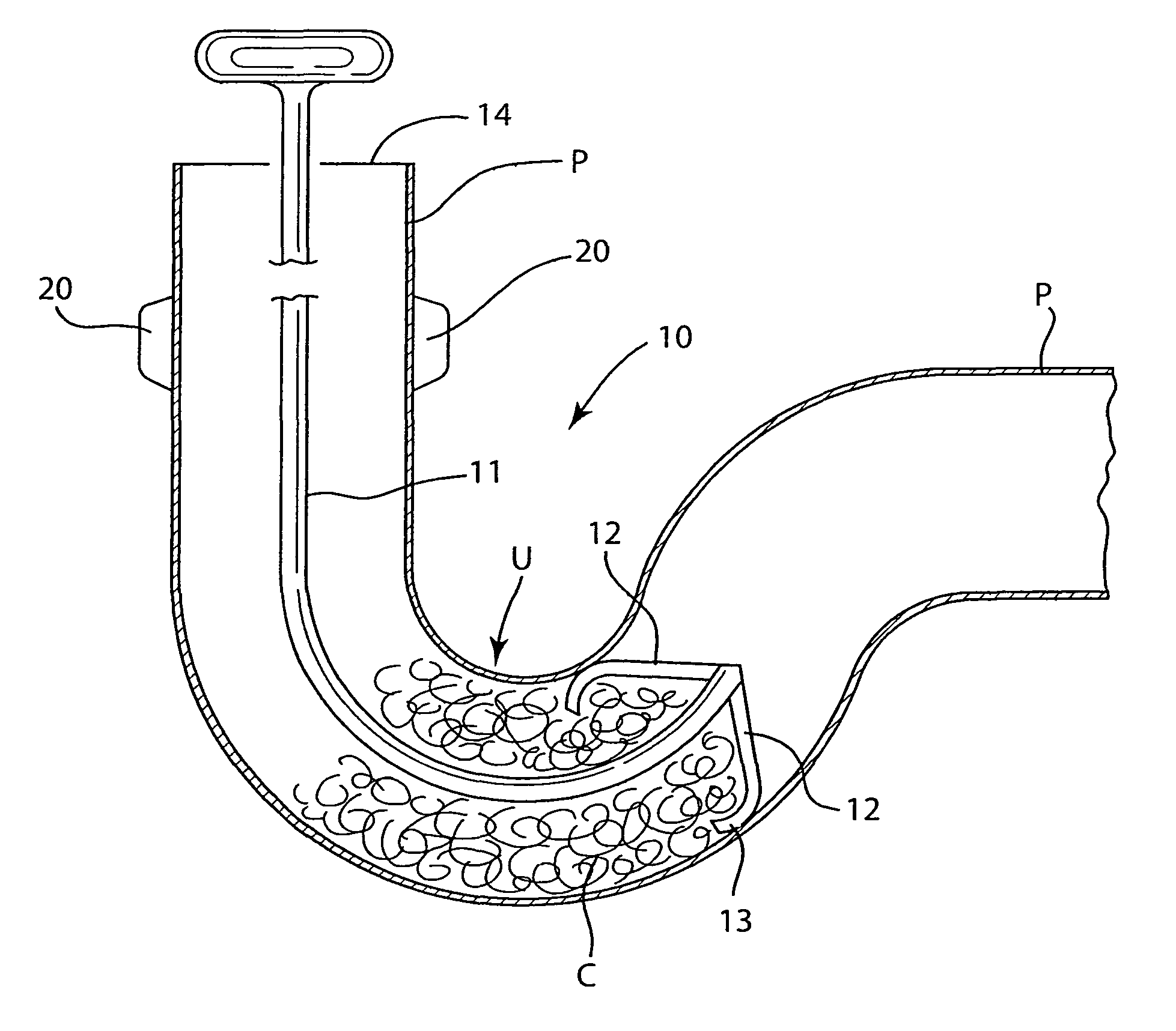
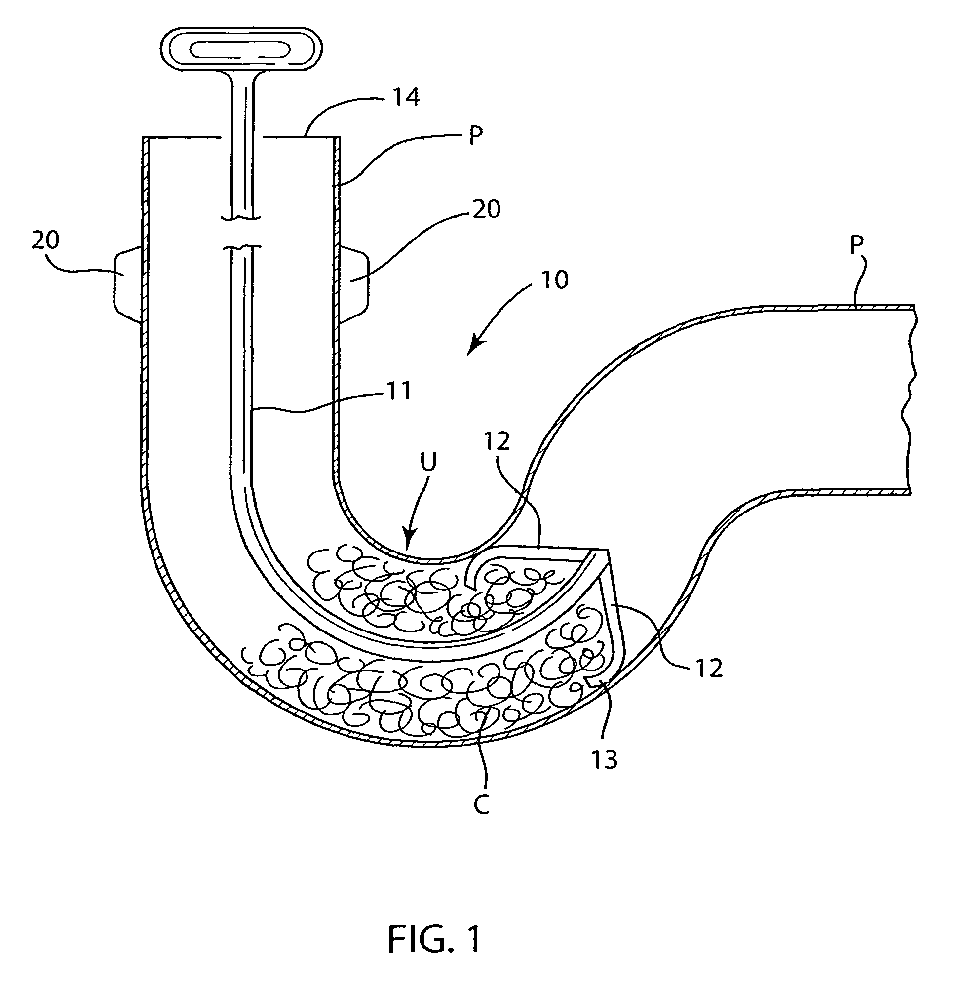
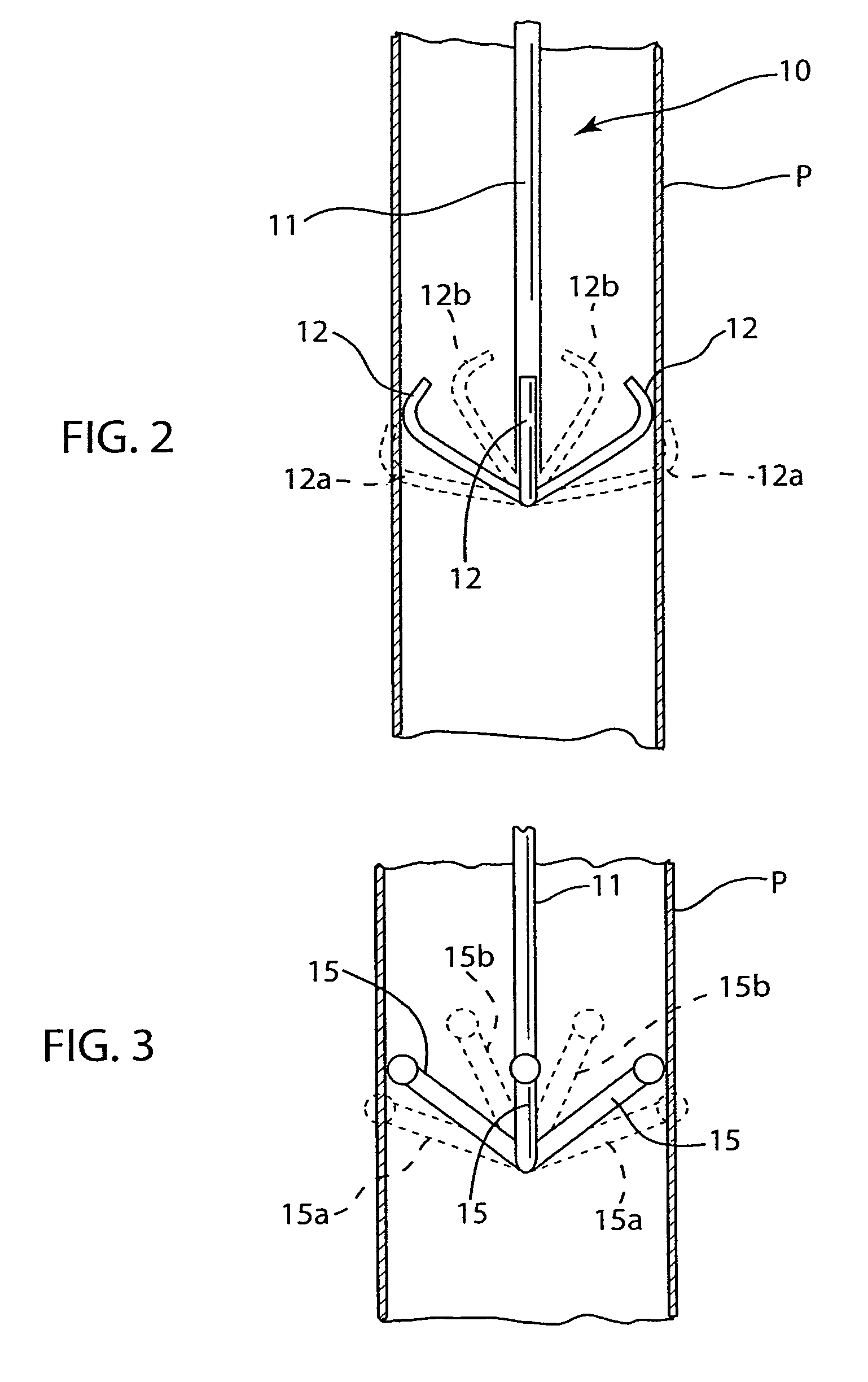
[0031]Referring now to the drawings, like elements are represented by like numerals throughout the several views. FIG. 1 illustrates the drain cleaning device 10 of the present invention in operation. An elongated rod 11 made of metal or plastic has sufficient rigidity that it does not buckle, while on the other hand it is sufficiently flexible to bend around curves in a pipe. The proximal end of the rod includes a handle or the like for the user to grasp the rod 11. As is typical in domestic drains, the pipe P has a U-shaped portion, which serves as a water seal U to prevent gases downstream of the pipe from discharging into the room above the drain opening 14. In a bathroom sink drainage pipe which includes a rod extending across the pipe to grasp a poppet valve, the poppet valve must be removed for the present invention to be used therein. In FIG. 1 the poppet valve has been removed. The fittings 20 represent diametrically opposed openings with holes through which a rod would ext...


PUM


Abstract

A drain cleaner for cleaning entangled obstructions such as a clog from a drain pipe such as a sink, tub or shower. A rod extending into the drain pipe is formed of a material which is either metal or plastic but stiff enough that it will not buckle but flexible enough to bend around curves. Arms connected to the distal end of the rod normally flex outwardly such that when the arms are inserted into the pipe they are resiliently flexed against the inside wall of the pipe, the arms being circumferentially spaced apart from each other to create spaces between them and each arm can each flex resiliently independent of the other arms. The device may push some of the clog through to be washed out of the pipe. Obstruction material which is not moved downstream will then be grasped by the arms as the arms move outwardly against the inside wall of the pipe. The rod is then pulled back rearwardly toward the drain opening and the arms catch the obstruction material which did not get flushed downstream, and pull the obstruction material rearwardly to and out of the drain opening. A method for cleaning a drain pipe using the device of the present invention.

Description

FIELD OF THE INVENTION[0001]This invention relates to cleaning obstructions from drain pipes.BACKGROUND OF THE INVENTION[0002]Drain pipes for drains of all types, including large industrial drains and smaller domestic drains such as in sinks, tubs and showers are susceptible to being blocked by obstructions. While it is understood that the principles of the present invention are applicable to all types of drain pipes, the invention will be described herein particularly with respect to domestic home drain pipes such as in sinks, tubs, showers and floor drains as may be found in a laundry room or basement.[0003]Drain pipes, especially of the type in a home, generally have a U-shaped water seal located just downstream of the drain opening wherein the drain pipe follows a U-shaped path, the purpose of such a water seal being to prevent gases and the like from passing from the inside of the pipe up into the room above the drain opening. The problem, however, is that this U-shaped water s...

Claims


Application Information

Patent Timeline
Patent Type & Authority Patents(United States)
IPC IPC(8): B08B9/045E03C1/302
CPCE03C1/302
Inventor PETRY, MARVIN
Owner PETRY MARVIN
Why Eureka
Try Eureka