Operational amplifier circuit

a technology of amplifier circuit and amplifier, which is applied in the direction of amplifier with semiconductor device/discharge tube, dc-amplifiers with dc-coupled stages, and differential amplifiers, etc., can solve the problems of increasing current consumption, and achieve the effect of reducing input offset voltage and low current consumption

Active Publication Date: 2015-12-22
ABLIC INC
View PDF7 Cites 1 Cited by
  • Summary
  • Abstract
  • Description
  • Claims
  • Application Information

AI Technical Summary

Benefits of technology

[0012]The operational amplifier circuit includes an amplifier stage, a FIR filter, and a sample and hold circuit that are connected in series, thus enabling reduction of an input offset voltage and amplification of an input signal voltage without using an integral circuit.
[0013]The operational amplifier circuit according to one embodiment of the present invention configured as described above is capable of reducing the input offset voltage without using an integral circuit. Consequently, the operational amplifier circuit according to one embodiment of the present invention has an effect that current consumption is low.

Problems solved by technology

However, this causes an increase in current consumption.

Method used


Image

  • Operational amplifier circuit
  • Operational amplifier circuit
  • Operational amplifier circuit

Examples


Embodiment Construction

[0017]Now, an exemplary embodiment of the present invention is described with reference to the accompanying drawings.

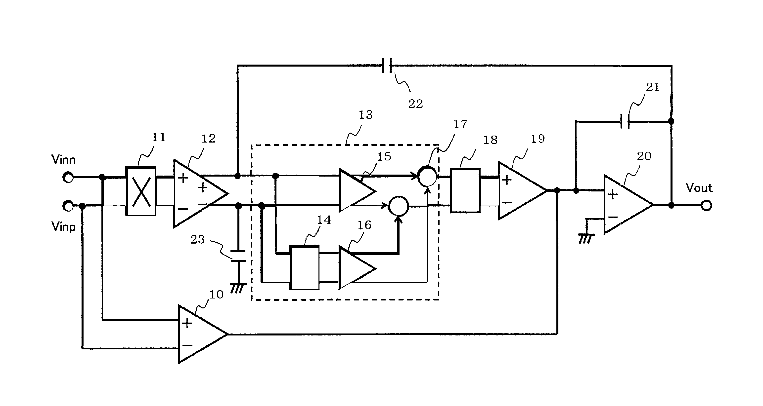
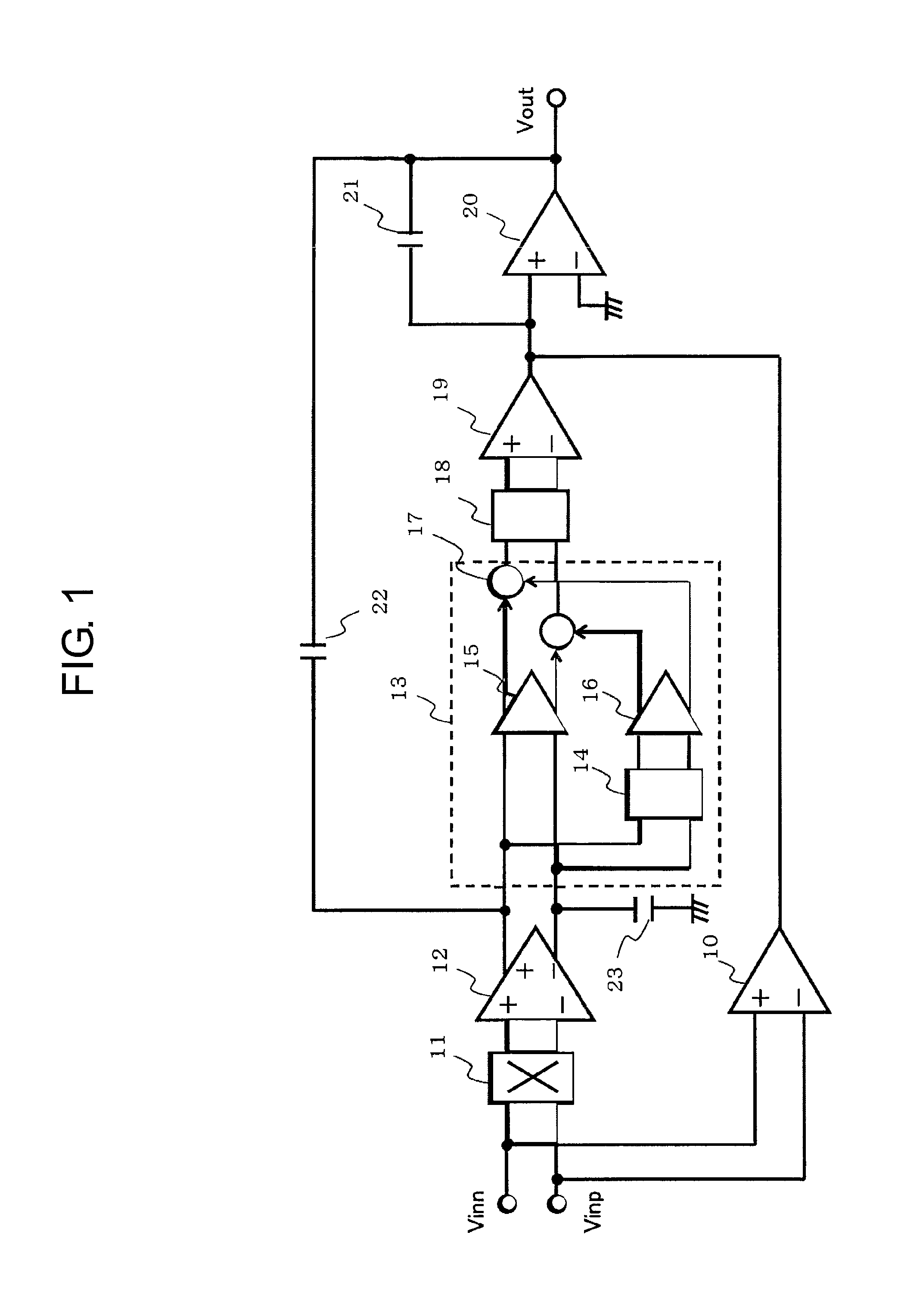
[0018]First, a configuration of an operational amplifier circuit is described. FIG. 1 is a block diagram illustrating an operational amplifier circuit according to the embodiment of the present invention.

[0019]The operational amplifier circuit according to the embodiment of the present invention includes an amplifier stage 10, a chopping circuit 11, an amplifier stage 12, a FIR filter 13 including a delay circuit 14, a weighting circuit 15, a weighting circuit 16, and an adder circuit 17, a sample and hold circuit 18, an amplifier stage 19, an amplifier stage 20, a phase compensating capacitor 21, a phase compensating capacitor 22, and a phase compensating capacitor 23.

[0020]The chopping circuit 11 has input terminals connected to input terminals Vinn and Vinp of the operational amplifier circuit. The amplifier stage 12 has input terminals connected to output terminal...


PUM


Abstract

Provided is an operational amplifier circuit capable of operating with lower current consumption. An amplifier stage, a FIR filter, and a sample and hold circuit are connected in series, thus enabling reduction of an input offset voltage and amplification of an input signal voltage without using an integral circuit. Current consumption of the operational amplifier circuit is reduced because the integral circuit is not used.

Description

RELATED APPLICATIONS[0001]This application claims priority under 35 U.S.C. §119 to Japanese Patent Application No. 2013-036211 filed on Feb. 26, 2013, the entire content of which is hereby incorporated by reference.BACKGROUND OF THE INVENTION[0002]1. Field of the Invention[0003]The present invention relates to an operational amplifier circuit.[0004]2. Description of the Related Art[0005]FIG. 3 is a diagram illustrating a related-art operational amplifier circuit.[0006]When a signal voltage is input to input terminals Vinn and Vinp, the signal voltage is modulated into a high frequency wave by a chopping circuit 81. The modulated signal voltage is input to an amplifier stage 82 and amplified. At this time, an input offset voltage of the amplifier stage 82 is also amplified simultaneously together with the modulated signal voltage. An output voltage of the amplifier stage 82 is input to a chopping circuit 83, and the signal voltage is demodulated and the input offset voltage of the am...

Claims


Application Information

Patent Timeline
Patent Type & Authority Patents(United States)
IPC IPC(8): H03F1/02H03F3/387H03F3/45
CPCH03F3/387H03F3/45475H03F3/45968H03F2203/45138H03F2200/261
Inventor TOMIOKA, TSUTOMU
Owner ABLIC INC
Why Eureka
Try Eureka