Fixed-focus lens

a fixed-focus lens and lens technology, applied in the field of lenses, can solve the problems of unfavorable outdoor operations and relatively high cost of cemented lenses, and achieve the effect of low manufacturing cost and high temperature toleran

Active Publication Date: 2016-02-16
YOUNG OPTICS
View PDF20 Cites 8 Cited by
  • Summary
  • Abstract
  • Description
  • Claims
  • Application Information

AI Technical Summary

Benefits of technology

[0007]The invention is directed to a fixed-focus lens having low manufacturing cost and high temperature tolerance.
[0010]Based on above, in embodiments of the invention, the cemented lens in the fixed-focus lens is replaced by multiple lenses separated from each other. Therefore, apart from effectively reducing the manufacturing cost, risks in glue failure of the cemented lens could also be avoided, so as to allow the fixed-focus lens in providing the high temperature tolerance.
[0011]Moreover, the invention could also provide characteristics including wide-angle, low f-number, con-focal effect of visible light / infrared light, small in volume and low in costs.

Problems solved by technology

Although the cemented lens is conducive in reducing an aberration and a chromatic aberration of the wide-angle lens, a cost thereof is relatively higher.
Also, when operating in a high temperature environment, the cemented lens is not conducive in the outdoor operations due to risks in glue failure.

Method used


Image

  • Fixed-focus lens
  • Fixed-focus lens
  • Fixed-focus lens

Examples


first embodiment

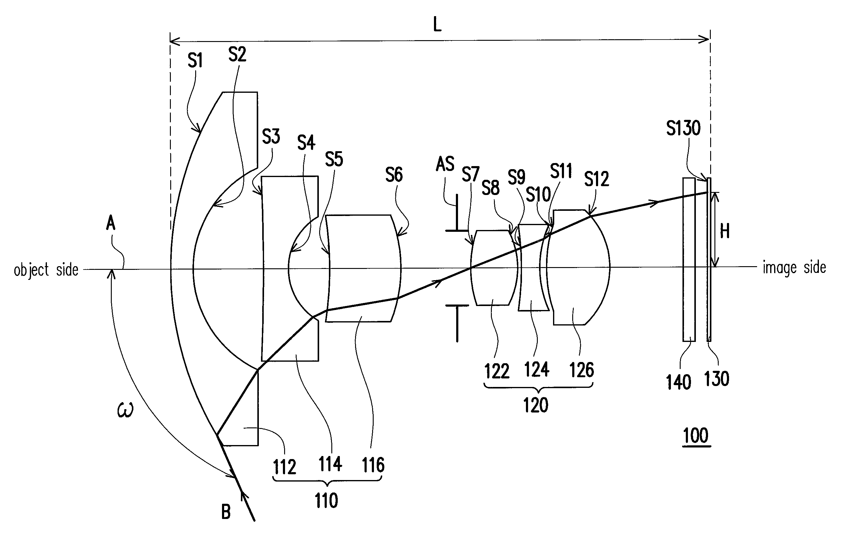
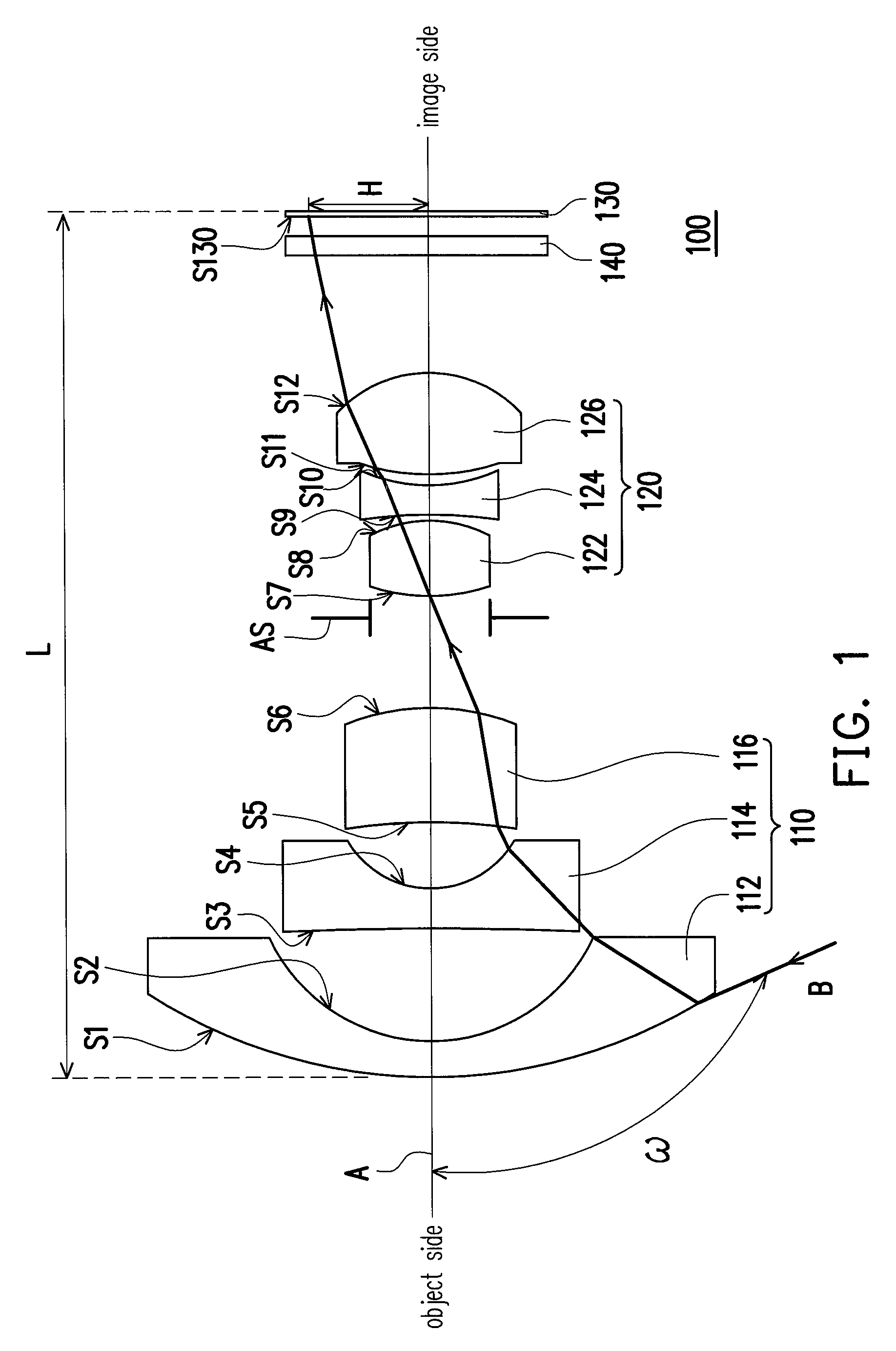
[0022]FIG. 1 is a schematic diagram of a fixed-focus lens according to first embodiment of the invention. Referring to FIG. 1, a fixed-focus lens 100 of the embodiment includes a first lens group 110 and a second lens group 120, in which the first lens group 110 and the second lens group 120 are arranged along an optical axis A of the fixed-focus lens 100 and located between an object side and an image side.

[0023]The first lens group 110 includes a first lens 112, a second lens 114 and a third lens 116 arranged in sequence from the object side to the image side, and refractive powers of the first lens 112, the second lens 114 and the third lens 116 are negative, negative, and positive in sequence, such that the first lens group 110 is provided with a negative refractive power. Accordingly, besides that a light beam B with a field of view (2ω, in which ω is a half angle of the field of view) greater than 180 degrees or even exceeding 210 degrees could be received, the first lens grou...

second embodiment

[0043]FIG. 6 is a schematic diagram of a fixed-focus lens according to second embodiment of the invention. Referring to FIG. 6, a fixed-focus lens 200 of the embodiment is similar to the fixed-focus lens 100 depicted in FIG. 1, and a major difference thereof is selections of curvature radius, the distance and the spheric / aspheric lenses for said lenses. Preferable parameter values of the fixed-focus lens 200 are listed in Table 3 and Table 4 below. However, the invention is not limited to the data listed below. It should be known to those ordinary skilled in the art that various modifications and variations can be made to the structure of the invention without departing from the scope or spirit of the invention.

[0044]

TABLE 3CurvatureDistanceLensesSurfaceradius (mm)(mm)Dispersion ValueFirst LensS112.440.75S24.642.80Second LensS3−20.510.80S42.161.81Third LensS5−6.622.00S6−3.291.29Aperture StopInfinity0.78Fourth LensS75.701.7781.6S8−2.960.10Fifth LensS9−23.110.80S102.430.17Sixth LensS1...


PUM


Abstract

A fixed-focus lens including a first lens group and a second lens group is provided. The first lens group having a negative refractive power includes a first lens, a second lens and a third lens arranged in sequence from an object side to an image side, in which refractive powers of the first, second and third lenses are negative, negative and positive in sequence. The second lens group having a positive refractive power is located between the first lens group and the image side, and the second lens group includes a fourth lens, a fifth lens and a sixth lens arranged in sequence from the object side to the image side, in which refractive powers of the fourth, fifth and sixth lenses are positive, negative and positive in sequence. The first, second, third, fourth, fifth and sixth lenses are separated from each other.

Description

CROSS-REFERENCE TO RELATED APPLICATION[0001]This application claims the priority benefit of Taiwan application serial no. 102130850, filed on Aug. 28, 2013. The entirety of the above-mentioned patent application is hereby incorporated by reference herein and made a part of this specification.BACKGROUND OF THE INVENTION[0002]1. Field of the Invention[0003]The invention generally relates to a lens, and more particularly to a fixed-focus lens.[0004]2. Description of Related Art[0005]With advances in optical-electronic technologies, an image apparatus such as digital video camera (DVC) and digital camera (DC) has been widely applied in daily life. Lens is one of main elements in the image apparatus, and configured to render images clearly on a screen or a charge coupled device (CCD). In case the image apparatus are applied in specific fields, a wide angle lens is adopted to increase a field of view (FOV). For instance, the wide angle lens is needed and adopted in a car back-up camera, a...

Claims


Application Information

Patent Timeline
Patent Type & Authority Patents(United States)
IPC IPC(8): G02B9/10G02B13/18G02B3/02G02B13/04G02B9/62
CPCG02B9/10G02B3/02G02B9/62G02B13/04G02B13/18G02B15/177
Inventor LAI, SHENG-TANGWANG, KUO-CHUAN
Owner YOUNG OPTICS
Why Eureka
Try Eureka