Unlock instant, AI-driven research and patent intelligence for your innovation.

Head mounted display and display control method

a display and display control technology, applied in the field can solve the problems of not intending to perform luminance adjustment for head mounted displays, and affecting the operation of head mounted displays. , to achieve the effect of excellent head mounted displays and display control, reducing luminance in response, and long life of display devices

Inactive Publication Date: 2016-04-19
SONY CORP
View PDF13 Cites 5 Cited by
  • Summary
  • Abstract
  • Description
  • Claims
  • Application Information

AI Technical Summary

Benefits of technology

The technology described in this patent allows for the creation of a long-life head mounted display that is less likely to develop burn-in and a display control method that adjusts the luminance based on the viewer's view sensitivity. This helps to improve the viewer's experience and allow for extended periods of viewing, such as for watching movies or playing games. Additionally, the technology helps to reduce the dazzle feeling that can occur when viewing through a showing apparatus that directly covers the eyes, by controlling the luminance based on the viewer's limited dark adaptation.

Problems solved by technology

It is known in the industry that if the display panel constituted by the liquid crystal, the organic EL device, or the like continues to display high luminance images, a burn-in phenomenon becomes likely to occur.
However, either of the above-described conventional technologies does not intend to perform an adjustment of luminance for a head mounted display.
Furthermore, when mounting the head mounted display with a light shielding feature, the eyes of the viewer are shielded from environmental light, and therefore it makes no sense to measure the illumination intensity in the viewing environment.

Method used


Image

  • Head mounted display and display control method
  • Head mounted display and display control method
  • Head mounted display and display control method

Examples


Embodiment Construction

[0041]Hereinafter, preferred embodiments of the technology disclosed in the description will be described in detail with reference to the appended drawings.

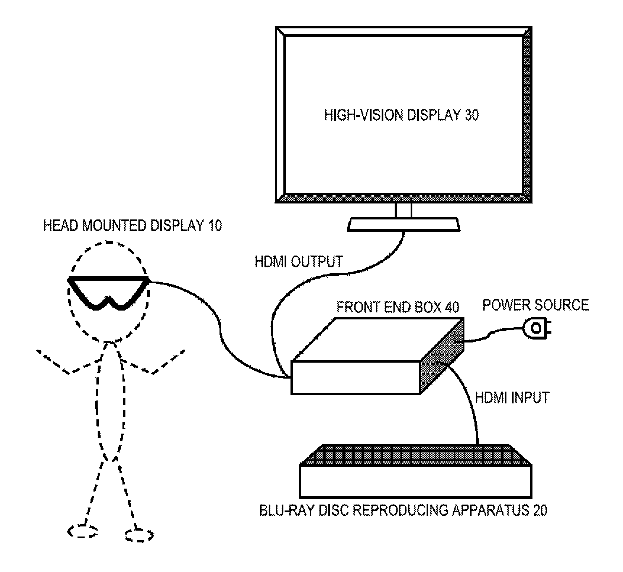
[0042]FIG. 1 schematically illustrates a configuration of an image display system including the head mounted display. The system illustrated includes a head mounted display 10 itself, a Blu-ray disc reproducing apparatus 20 as a source of view content, a high-vision display (e.g. HDMI (High-Definition Multimedia Interface) television) 30 as other output destination of playback content of the Blu-ray disc reproducing apparatus 20, and a front end box 40 that performs processing of an AV signal output from the Blu-ray disc reproducing apparatus 20.

[0043]The front end box 40 corresponds to an HDMI repeater that, when receiving an HDMI input of an AV signal output from the Blu-ray disc reproducing apparatus 20, performs signal processing and HDMI output, for example. Also, the front end box 40 also denotes a two-way output switcher t...


PUM


Abstract

Provided is a head mounted display including a displaying unit to display an image, an image signal processing unit to process an image signal, a display control unit to perform an image quality adjustment of the image signal processed by the image signal processing unit, and to control a display in the displaying unit, a mounting sensor to detect whether an observer has mounted the apparatus, and a control unit to issue an instruction for the image quality adjustment of the image signal in the display control unit, in response to a detection result by the mounting sensor.

Description

CROSS-REFERENCE TO RELATED APPLICATION[0001]The present application is a national phase entry under 35 U.S.C. §371 of International Application No. PCT / JP2012 / 075778 filed Oct. 4, 2012, published on Apr. 18, 2013 as WO 2013 / 054728 A1, which claims priority from Japanese Patent Application No. JP 2011-223935 filed in the Japanese Patent Office on Oct. 11, 2011.TECHNICAL FIELD[0002]The technology disclosed in the description relates to a head mounted display that is mounted on the head of a user and is utilized for viewing an image, and a display control method thereof, in particular, to a head mounted display and a display control method that achieve a long life of a display device to be used for displaying right and left images.BACKGROUND ART[0003]There is widely known a displaying apparatus mounted on a head to view an image, that is, a head mounted display (HMD). The head mounted display has an optical unit for each of right and left eyes and is configured to be able to control th...

Claims


Application Information

Patent Timeline
Patent Type & Authority Patents(United States)
IPC IPC(8): G02B27/01G09G3/00H04N13/04G02B27/00
CPCG02B27/017G02B27/0093G02B27/01G09G3/001H04N13/044H04N13/0497G02B2027/014G02B2027/0118G02B2027/0178G09G2320/02G09G2320/0271G09G2340/00G09G2360/144H04N2213/008H04N13/344H04N13/398
Inventor TAKAHASHI, NAOMASAHIROTA, YOICHIKAJI, YOHSUKENABETA, MASAOMIITOU, HIROAKI
Owner SONY CORP