Brake caliper with brake pad timing and retraction controller

a brake caliper and controller technology, applied in the field of brake calipers, can solve the problems of insufficient frictional engagement between the collar and the bolt shaft, the controller damps out-of-plane vibration between the brake pad and the rotor, and the mechanism is self-adjusting, so as to achieve the effect of easy and reliable adjustment of timing and clamping for

Active Publication Date: 2016-12-06
PERFORMANCE FRICTION
View PDF66 Cites 6 Cited by
  • Summary
  • Abstract
  • Description
  • Claims
  • Application Information

AI Technical Summary

Benefits of technology

[0005]Accordingly, the applicants have observed that there is a need for a brake caliper having a brake pad timing and retraction controller that can easily and reliably adjust the timing and clamping force of the brake pad extension when the brake pedal is depressed, and that can positively and uniformly retract the brake pad from the rotor when the brake pad is released. To this end, the brake caliper of the invention comprises a caliper housing, a brake pad having a braking surface that selectively engages a brake rotor, at least one reacting member such a hydraulic piston mounted in the housing that extends and retracts the brake pad into and out of frictional engagement with said rotor; and a brake pad timing and retraction controller including at least one resilient member with limited compression travel.
[0006]The brake pad timing and retraction controller biases against extension by applying an adjustable hold-off force against an extension force applied to said brake pad by said reacting member that momentarily delays extension and slightly reduces the resulting clamping force between the brake pad and the rotor. The controller also forces positive and uniform retraction of the brake pad from the rotor, thereby minimizing parasitic braking. Additionally, the controller positively retracts the brake pad from the rotor a consistent distance throughout the wear life of the brake pad and rotor, rendering the mechanism self-adjusting. The controller also damps out-of-plane vibration between the brake pad and rotor. Advantageously, the use of separate controllers on opposing brake pads in an opposing brake caliper results in the application of independent pull back forces on the pads, thereby insuring that both pads will be positively and uniformly retracted out of engagement with the rotor.
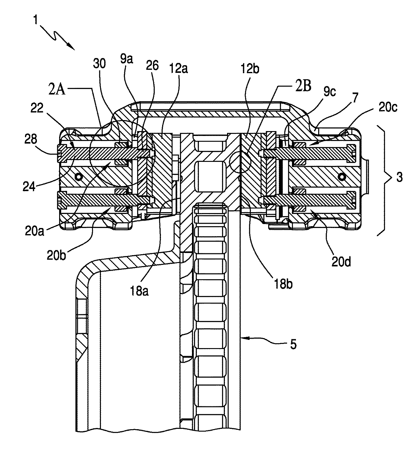
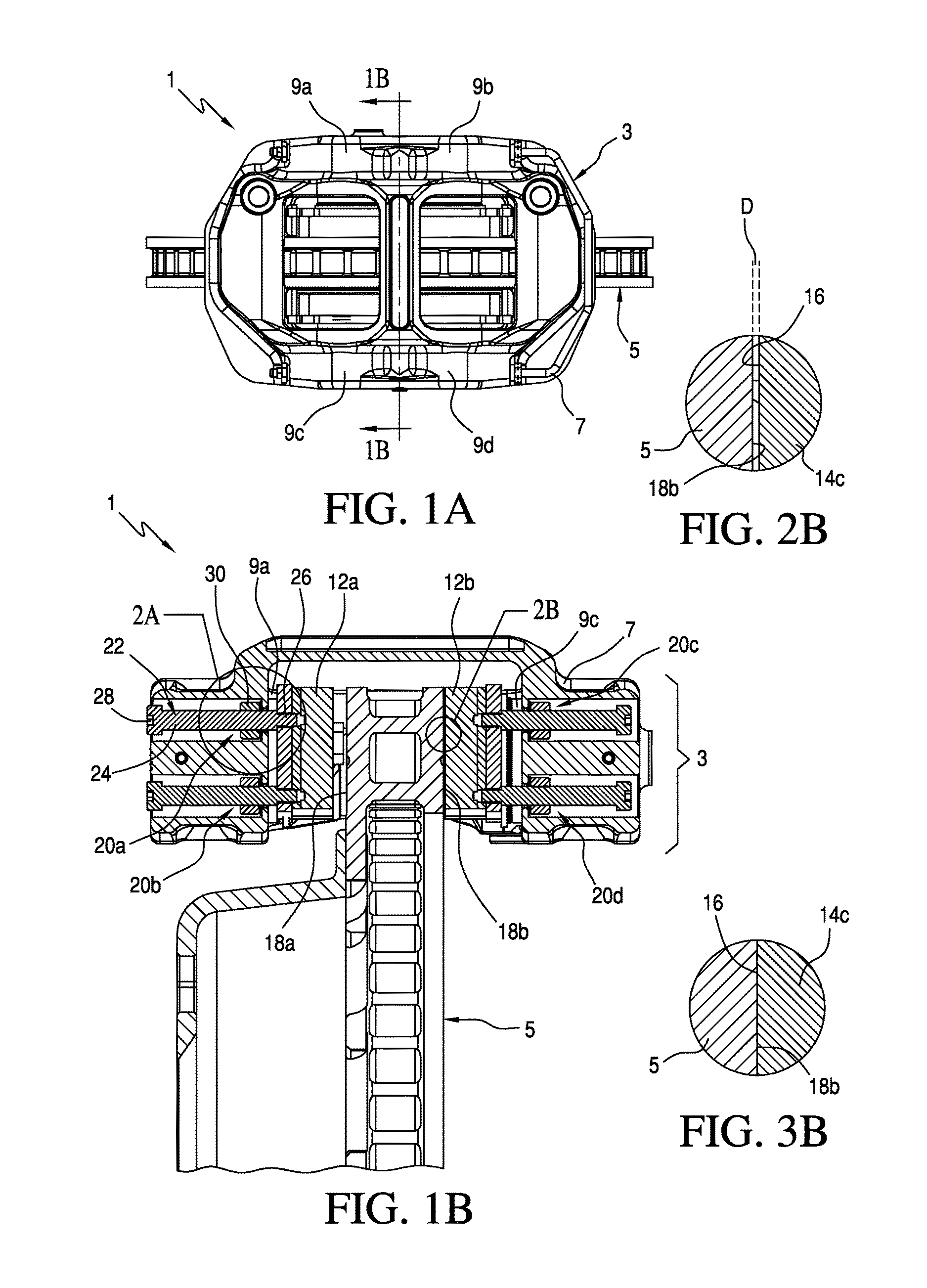
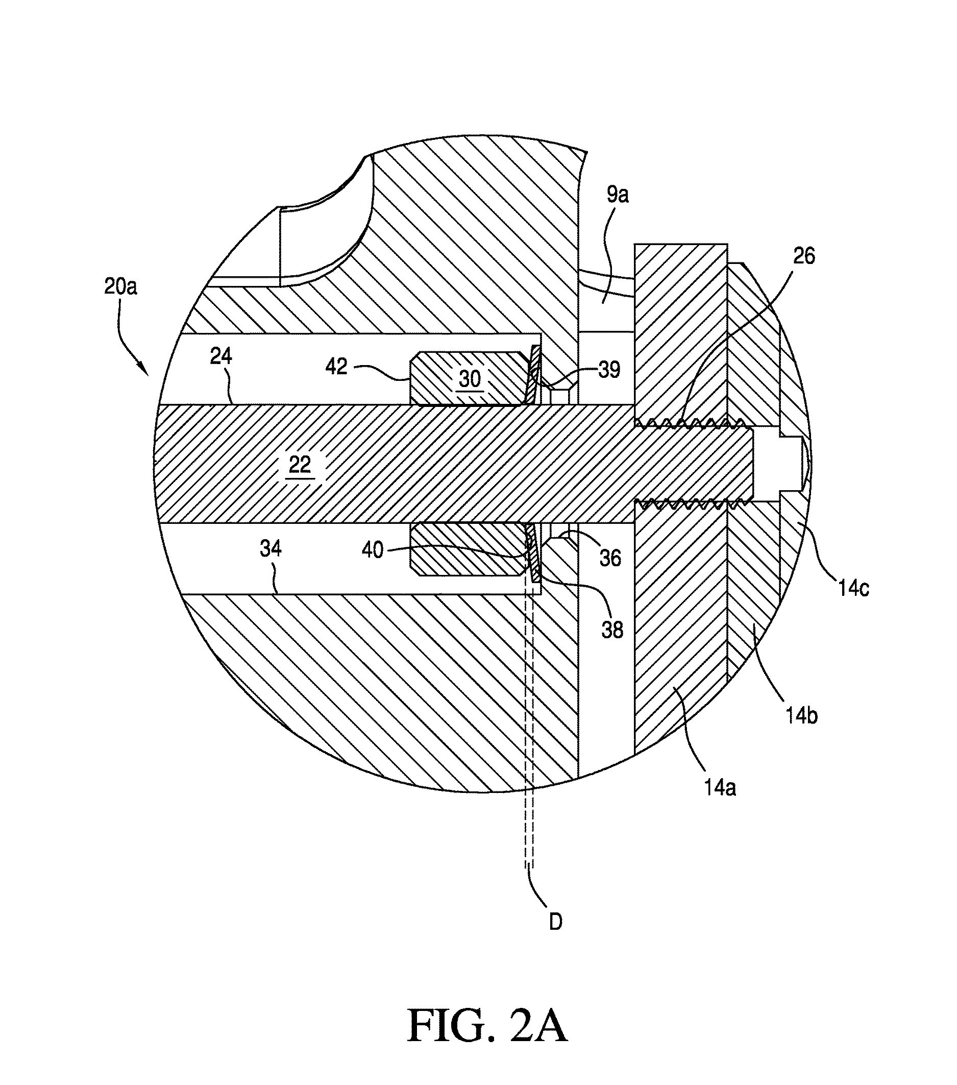
[0007]The brake pad timing and retraction controller includes a bolt having a shaft that includes an end prepared for attachment to the brake pad which may be a threaded end. The threaded end is connected to the brake pad, and the shaft is movably mounted with respect to the housing. The controller also includes a caliper retraction collar, which acts as a compression travel limiter, frictionally engaged but slidably movable on the bolt shaft and spaced apart from the threaded end, and the caliper housing includes first and second telescoping bores slightly larger than the bolt shaft and the collar, respectively, for slidably receiving the threaded end and the piston retraction collar. The resilient member is captured between the caliper retraction collar and the annular interface between the first and second counter bores. The frictional engagement between the collar and bolt shaft is sufficient to prevent the collar from sliding on said shaft in response to the spring force of the resilient member when the resilient member is completely compressed. However, the frictional engagement between the collar and bolt shaft is insufficient to prevent the collar from sliding on the shaft in response to the extension force applied to the brake pad by the reacting member. Consequently, the wearing down of the pad will cause the reacting member to incrementally slide the collar along the bolt shaft the same distance as the reduction in thickness of the pad due to wear. Such a structure advantageously allows the brake caliper to be self-adjusting in response to brake pad wear, thereby maintaining a constant-distance brake stroke throughout the life of the brake pad.
[0009]The brake caliper of the invention may be used in combination with a brake of an automotive vehicle. The spring force of the resilient member is preferably selected to create a momentary delay and a hold-off force against the extension force of the reacting member that results in a slight relative reduction in brake clamping force between the operation of, for example, the rear brakes and the front brakes. Accordingly, the invention may be used to provide front brake bias during the entire braking operation, thereby maximizing control of the vehicle during the braking operation. Such a desired momentary delay and slight reduction in clamping force of the rear brakes verses the front brakes may be accomplished by applying the caliper of the invention to the rear brakes only, but is more preferably accomplished by applying the caliper of the invention to the brakes of both the front and rear wheels, with the spring properties (i.e. travel distance or spring force) of the resilient member being different between the rear brake calipers and the front brake calipers in response to the actuation forces applied by the reacting members. Alternatively, left wheel-right wheel brake timing biases may also be implemented by the invention, which may be useful in certain race car driving applications.
[0010]Unexpectedly, the applicants have observed that the restorative force of the resilient member used in the brake pad timing and retraction controller not only advantageously adjusts brake timing, but also substantially increases the effective miles obtained per gallon of fuel and reduces brake wear due to a substantial decrease in parasitic braking. Further unexpectedly, the applicants have observed that the resiliency provided by the resilient member used in the brake pad timing and retraction controller also damps out-of-plane vibration between the brake pad and rotor, thereby reducing brake squeal.

Problems solved by technology

Additionally, the controller positively retracts the brake pad from the rotor a consistent distance throughout the wear life of the brake pad and rotor, rendering the mechanism self-adjusting.
The controller also damps out-of-plane vibration between the brake pad and rotor.
However, the frictional engagement between the collar and bolt shaft is insufficient to prevent the collar from sliding on the shaft in response to the extension force applied to the brake pad by the reacting member.
Consequently, the wearing down of the pad will cause the reacting member to incrementally slide the collar along the bolt shaft the same distance as the reduction in thickness of the pad due to wear.

Method used


Image

  • Brake caliper with brake pad timing and retraction controller
  • Brake caliper with brake pad timing and retraction controller
  • Brake caliper with brake pad timing and retraction controller

Examples


Embodiment Construction

[0023]FIGS. 1A and 1B illustrate a brake assembly 1 including the brake caliper 3 of the invention in combination with a rotor 5 attached to a wheel hub (not shown) which may be the wheel hub of an automotive vehicle. In this example of the invention, brake caliper 3 includes a housing 7 in which two pairs of opposing hydraulic caliper pistons 9a, 9b and 9c, 9d are slidably mounted within cylinders (not shown). Opposing brake pads 12a, 12b each include a backing plate 14a, and an underlayer 14b that secures a layer of pad material 14c to the backing plate 14a. Opposing brake pads 12a, 12b are mounted on the ends of the opposing caliper pistons 9a, 9b via the backing plate 14a. The brake pads 12a, 12b each have an engagement surface 16 which is adjacent to and engageable with one of the flat, opposing annular engagement surfaces 18a, 18b of the rotor 5 as is best shown in FIG. 1B. It should be noted that hydraulic pistons 9a, 9b and 9c, 9d are only one example of reacting members whi...


PUM


Abstract

A brake caliper is provided with a timing and retraction controller that that adjusts brake timing, eliminates parasitic brake losses and dampens out-of-plane vibration between the brake pad and rotor. The brake caliper includes a housing disposed over a brake rotor; first and second opposing brake pads extendably and retractably mounted on opposite sides of the caliper housing, brake pistons that extend and retract the brake pads into and out of frictional engagement with the rotor, and brake pad timing and retraction controllers disposed on opposite sides of the caliper housing. Each controller includes a Belleville spring or other resilient member with a short compression travel limited to between about 1.50 mm and 0.025 mm. The short stroke Belleville spring of each controller applies a hold-off force against the extension force of the brake pistons that slightly delays brake pad extension and slightly reduces brake pad clamping force against the rotor, thereby advantageously providing a front wheel braking bias when applied to the rear wheels of a vehicle. The restorative force applied by the short stroke Belleville forcefully and uniformly retracts the brake pad from the rotor, eliminating parasitic brake losses, and dampening out-of-plane vibration between the brake pad and rotor.

Description

RELATED APPLICATIONS[0001]This application claims the priority of U.S. Provisional Application No. 61 / 255,024 filed Oct. 26, 2009.FIELD OF THE INVENTION[0002]This invention generally relates to brake calipers, and is specifically concerned with a brake caliper having a brake pad timing and retraction controller that both adjustably delays and negatively biases brake pad extension force when the brake pedal is depressed and forces positive and uniform retraction of the brake pad when the brake pedal is released.BACKGROUND OF THE INVENTION[0003]Brake calipers for automotive disc brakes are well known in the prior art. In typical disc brake assemblies, a rotor is mounted on a wheel hub for rotation. One or more pairs of brake pads, generally designed as friction material carried on a backing plate, are supported on either side of the rotor by a caliper or an anchor bracket. Calipers are designed to apply the braking force by moving a piston relative to the rotor to move the brake pad i...

Claims


Application Information

Patent Timeline
Patent Type & Authority Patents(United States)
IPC IPC(8): F16D65/54F16D65/18F16D121/02F16D127/02
CPCF16D65/54F16D65/18F16D2121/02F16D2127/02F16D2125/582
Inventor BURGOON, DONALD L.BABBAGE, PETER N.MURTHY, NIHALCATE, DARIN E.
Owner PERFORMANCE FRICTION
Why Eureka
Try Eureka