Liquid crystal display device, backlight module, and drive circuit for backlight source thereof

a technology of backlight source and display device, which is applied in the direction of static indicating device, instrument, semiconductor lamp usage, etc., can solve the problems of limited capacity of current led driver ic in adjusting current, large error in value of current flowing through led, and inability to achieve predetermined current value, etc., to achieve the effect of reducing errors

Active Publication Date: 2017-06-06
TCL CHINA STAR OPTOELECTRONICS TECH CO LTD
View PDF6 Cites 0 Cited by
  • Summary
  • Abstract
  • Description
  • Claims
  • Application Information

AI Technical Summary

Benefits of technology

[0009]One of the technical problems to be solved by the present disclosure is to provide a backlight drive circuit, which can enable the current flowing through an LED to reach an adjustable range, and to approach a predetermined value with reduced errors. The present disclosure further provides a liquid crystal display device and a backlight module.
[0021]Compared with the prior art, one or more embodiments of the present disclosure has the following advantages.
[0022]According to the present disclosure, the circuit for automatic adjustment of current is incorporated into the backlight drive circuit, and thus can alter the value of a resistor in series connection to the LED when the current flowing through the LED extends the adjustable range of the controller, e.g., the constant-current LED driver IC. Thus, the current flowing through the LED can be adjusted to reach the adjustable range of the constant-current LED driver IC, and to increasingly approach a predetermined value (which can be calculated according to the working voltage) with reduced errors.

Problems solved by technology

However, the constant-current LED driver IC has limited capacity in adjusting currents due to a manufacturing procedure of a semiconductor and price factors.
As a result, a predetermined current value will not be achieved through adjustment by the constant-current LED driver IC beyond a specific range.
In addition, when the above circuit is used, the value of the current flowing through the LED would be subject to relatively large errors with respect to the predetermined current value.
Therefore, it is a major issue in the art to solve the above problem, so as to adjust the current flowing through the LED to a predetermined value with reduced errors.

Method used


Image

  • Liquid crystal display device, backlight module, and drive circuit for backlight source thereof
  • Liquid crystal display device, backlight module, and drive circuit for backlight source thereof
  • Liquid crystal display device, backlight module, and drive circuit for backlight source thereof

Examples


Embodiment Construction

[0029]In order to present the purpose, technical solution, and advantages of the present disclosure more explicitly, the present disclosure will be further explained in detail in connection with the accompanying drawings.

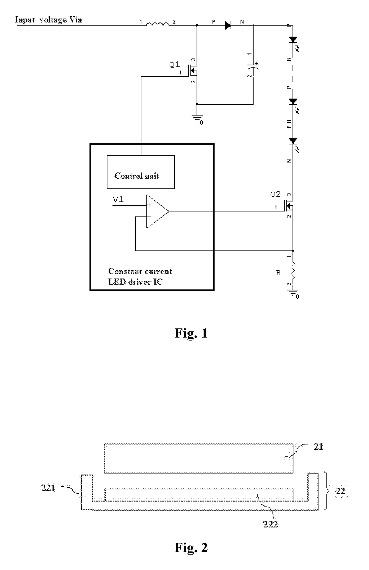
[0030]FIG. 2 schematically shows the structure of a liquid crystal display device according to an embodiment of the present disclosure. The structure of each component of the liquid crystal display device will be explained in the following with reference to FIG. 2.

[0031]As shown in FIG. 2, the liquid crystal display device comprises a liquid crystal display panel 21, and a backlight module 22 arranged opposite to the liquid crystal display panel 21. The backlight module 22 has a rear panel 221 and a backlight drive circuit 222. In the rear panel 221 there is provided with a space, which accommodates the backlight drive circuit 222 used for providing a required light source to the liquid crystal display panel 21.

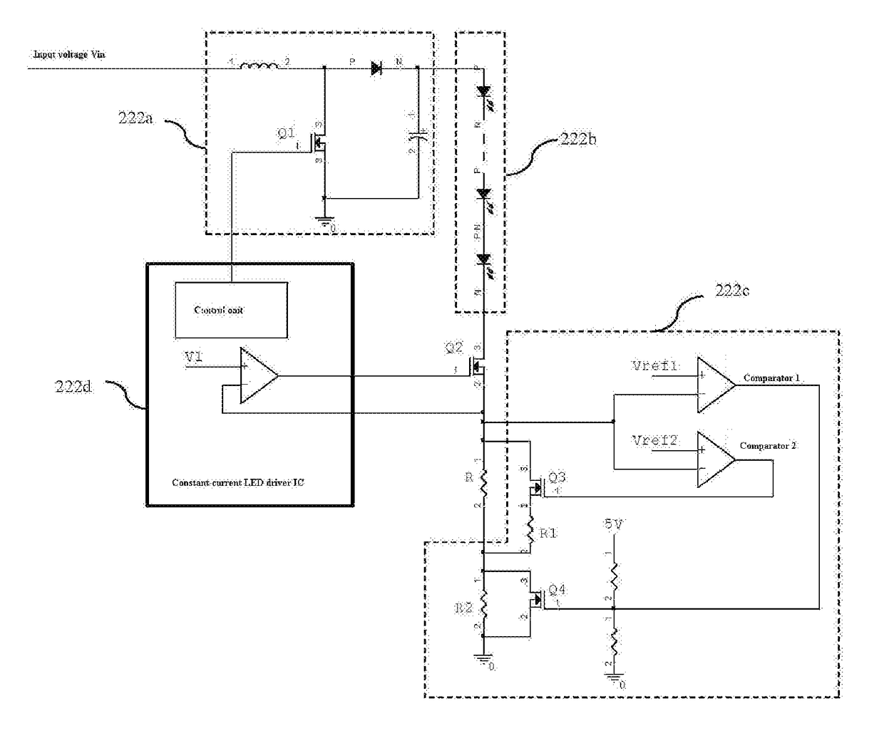
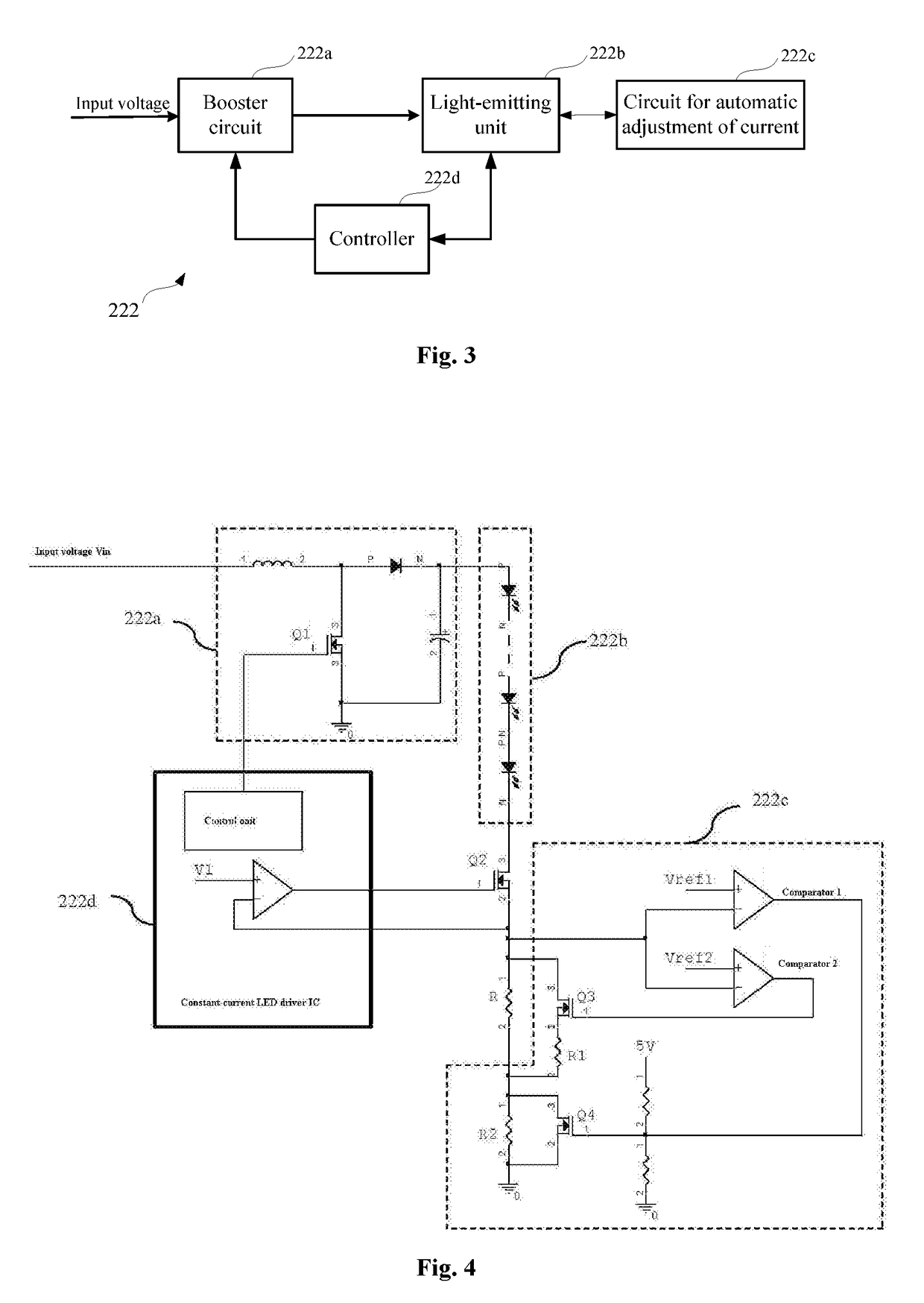
[0032]FIGS. 3 and 4 will be referred to in the followin...


PUM


Abstract

Disclosed is a liquid crystal display device, a backlight module, and a backlight drive circuit. The backlight drive circuit comprises a booster circuit, a light-emitting unit, a circuit for automatic adjustment of current, and a controller. The current flowing through an LED will be altered by the circuit for automatic adjustment of current when extending an adjustable range of the controller, so as to reach the adjustable range of the controller.

Description

CROSS-REFERENCE TO RELATED APPLICATIONS[0001]The present application claims benefit of Chinese patent application CN 201410798135.7, entitled “Liquid crystal display device, backlight module, and drive circuit for backlight source thereof” and filed on Dec. 18, 2014, the entirety of which is incorporated herein by reference.FIELD OF THE INVENTION[0002]The present disclosure relates to the technical field of liquid crystal displays, and in particular, to a liquid crystal display device, a backlight module, and a drive circuit for backlight source thereof.BACKGROUND OF THE INVENTION[0003]Recent years, in a thinning display trend, has witnessed wide use of liquid crystal displays (LCDs for short) in various electronic products, such as mobile phones, laptops, and color televisions.[0004]Because liquid crystals per se do not emit light, nor does an LCD panel itself have a light-emitting property, a lighting source, such as a backlight module, is necessary for an LCD. An image forms on t...

Claims


Application Information

Patent Timeline
Patent Type & Authority Patents(United States)
IPC IPC(8): G09G3/36H05B33/08G09G3/34H05B44/00
CPCG09G3/3648H05B33/0815H05B33/0818H05B33/0824G09G3/3406G09G2330/12H05B45/44Y02B20/30H05B45/38
Inventor ZHANG, HUACAO, DAN
Owner TCL CHINA STAR OPTOELECTRONICS TECH CO LTD
Why Eureka
Try Eureka