Liquid crystal panels and the driving circuits thereof

a technology of driving circuit and liquid crystal panel, which is applied in the direction of instruments, static indicating devices, etc., can solve the problems of increasing the power consumption of the source driver b>11, and reducing the power consumption of the source driving circuit. , to achieve the effect of reducing the switching range of the voltage and reducing the power consumption of the source driving circui

Active Publication Date: 2018-02-20
TCL CHINA STAR OPTOELECTRONICS TECH CO LTD +1
View PDF15 Cites 3 Cited by
  • Summary
  • Abstract
  • Description
  • Claims
  • Application Information

AI Technical Summary

Benefits of technology

[0008]The object of the invention is to provide a liquid crystal panel and the driving circuit thereof for reducing the power consumption of the driving circuit.
[0025]In view of the above, the output ends of each of the source driving circuit respectively connects to the sub-pixels having the same polarity within one scanning frame. Thus, within one scanning frame, the source driving circuit only needs to output the driving voltage with the same polarity. This prevents the source driving circuit from switching between the positive driving voltage and the negative driving voltage, which not only reduces the switching range of the voltage but also reduces the power consumption of the source driving circuit.

Problems solved by technology

However, in the above driving method, as the driving voltage of the four sub-pixels (RGBW) may be positive or negative, and thus the source driver 11 has to switch between the positive voltage and the negative voltage, which increases the power consumption of the source driver 11.
This prevents the source driving circuit from switching between the positive driving voltage and the negative driving voltage, which not only reduces the switching range of the voltage but also reduces the power consumption of the source driving circuit.

Method used


Image

  • Liquid crystal panels and the driving circuits thereof
  • Liquid crystal panels and the driving circuits thereof
  • Liquid crystal panels and the driving circuits thereof

Examples


Embodiment Construction

[0032]Embodiments of the invention will now be described more fully hereinafter with reference to the accompanying drawings, in which embodiments of the invention are shown.

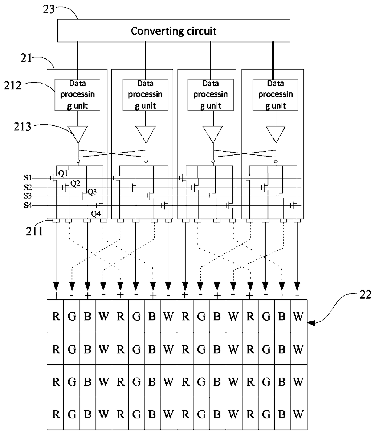
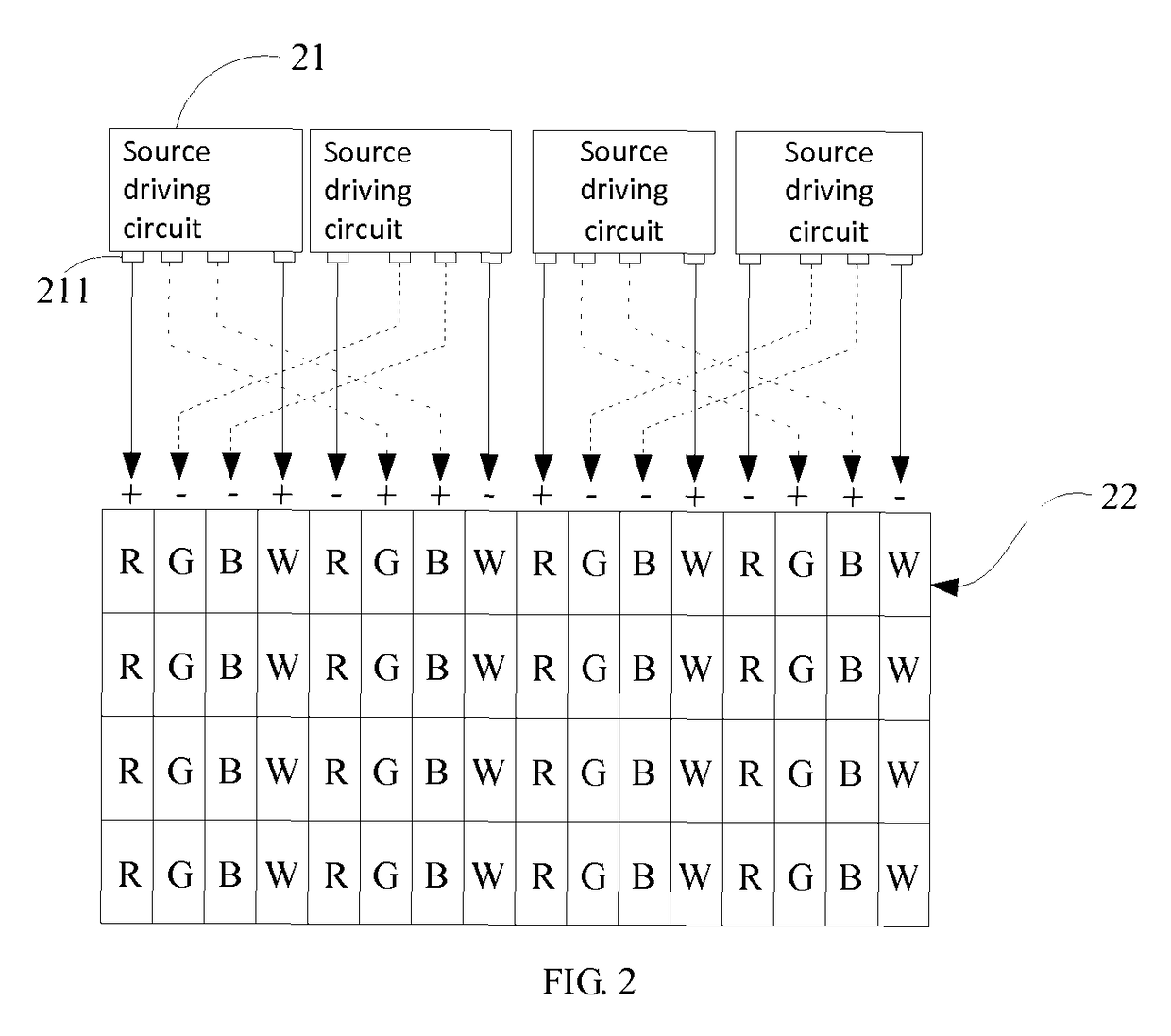
[0033]FIG. 2 is a schematic view of the liquid crystal panel in accordance with one embodiment. The liquid crystal panel includes a plurality of source driving circuits 21 and a plurality of sub-pixel rows 22. The source driving circuits 21 are arranged within an non-display area of the liquid crystal panel for providing the driving voltage to the sub-pixels. The sub-pixel rows 22 are arranged along a row direction, and are arranged within a display area of the liquid crystal panel so as to display images.

[0034]In the embodiment, each of the sub-pixel rows 22 includes a plurality of sub-pixels having different colors arranged periodically along the row direction. Each of the sub-pixel is defined by a data line and a scanning line. One sub-pixel row connects with one scanning line, and one sub-pixel column connect...


PUM


Abstract

The present disclosure relates to a liquid crystal panel and the driving circuit. The liquid crystal panel includes a plurality of source driving circuits and a plurality of sub-pixel rows extending along a row direction. Each of the sub-pixel rows includes a plurality of sub-pixels of different colors and the sub-pixels are arranged periodically along the row direction. Within one scanning frame, polarity of driving voltage of at least one sub-pixel within the arranging period is opposite to that of other sub-pixels. Each of the source driving circuit includes at least two output ends respectively connecting to at least two sub-pixels having the same polarity of driving voltage within the same scanning frame to provide the driving voltage of the same polarity to the at least two sub-pixels. In this way, the power consumption of the source driving circuit may be reduced.

Description

BACKGROUND OF THE INVENTION[0001]1. Field of the Invention[0002]The present disclosure relates to liquid crystal display technology, and more particularly to a liquid crystal panel and a driving circuit thereof.[0003]2. Discussion of the Related Art[0004]LCDs typically are characterized by attributes including thin, flicker-free, power-saving, and thus are the main trend of displays.[0005]The LCDs mainly rely on optical characteristics of liquid crystal to display. The driving voltage of liquid crystal molecules cannot be fixed at one value, or the liquid crystal molecules may be polarized and optical rotation features may disappear. To protect such features, usually, the liquid crystal panel may be driven by polarity inversion methods. At this moment, the driving voltage of the pixel electrodes may include two polarities. The polarity is positive when the driving voltage of the pixel electrode is greater than the voltage of the common electrode, and the polarity is negative when th...

Claims


Application Information

Patent Timeline
Patent Type & Authority Patents(United States)
IPC IPC(8): G09G3/36
CPCG09G3/3614G09G3/3607G09G3/3688G09G2330/021G09G2300/0452G09G2320/0247G09G2300/0804G09G2340/06
Inventor GUO, XINGLINGZHOU, JINJIEBAI, YUJIE
Owner TCL CHINA STAR OPTOELECTRONICS TECH CO LTD
Why Eureka
Try Eureka