
Ventilator with integrated cough-assist
a technology of ventilator and air intake, which is applied in the field of ventilator, can solve the problems of tedious process and particularly problematic travel with such equipmen
- Summary
- Abstract
- Description
- Claims
- Application Information
AI Technical Summary
Problems solved by technology
Method used
Image

Examples
first embodiment
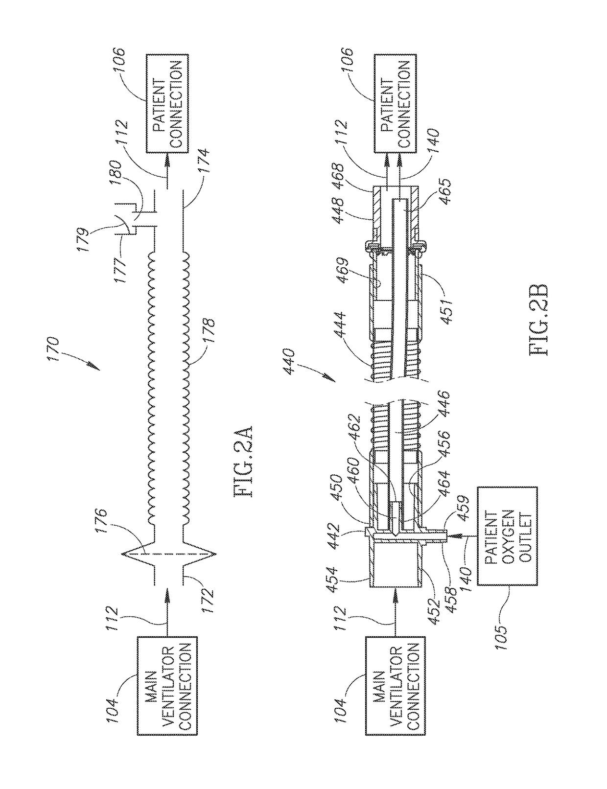
[0120]FIG. 2A is an illustration of a passive patient circuit 170 that may be used to implement the patient circuit 110. Referring to FIG. 2A, the passive patient circuit 170 has a first end portion 172 opposite a second end portion 174. The first end portion 172 is configured to be connected or coupled (e.g., directly or using a hose, flow line, conduit, or tube) to the main ventilator connection 104. The second end portion 174 is configured to be connected or coupled to the patient connection 106 (e.g., directly or using a hose, flow line, conduit, or tube). Optionally, a secretion trap 1250 (described below with respect to FIGS. 27-29) may be positioned between the second end portion 174 and the patient connection 106. The passive patient circuit 170 conducts the gases 112 (that include the air 114 optionally mixed with oxygen) from the main ventilator connection 104 into the patient connection 106 (optionally via the secretion trap 1250 illustrated in FIGS. 27-29).
[0121]In the e...
second embodiment
[0125]FIG. 2B is an illustration of a passive patient circuit 440 that may be used to implement the patient circuit 110. The passive patient circuit 440 includes a connector 442, a flexible tube segment 444, an open-ended oxygen pulse delivery tube 446, and a valve assembly 448. The flexible tube segment 444 may be implemented using a conventional corrugated or expanding ventilation hose or tubing (e.g., circuit tubing). The flexible tube segment 444 has a first end portion 450 opposite a second end portion 451. The first end portion 450 is configured to be connected or coupled to the connector 442. The second end portion 451 is configured to be connected or coupled to the valve assembly 448.
[0126]The connector 442 has a generally tube-shaped connector housing 452 with a first end portion 454 configured to be connected to the main ventilator connection 104 (e.g., directly or using a hose, flow line, conduit, or tube) and to receive the gases 112 (that include the air 114 optionally ...
PUM
 Abstract
Description
Claims
Application Information