
Pressure drum for water purifier and its production
A technology of water purification equipment and production process, applied in water/sewage treatment, water/sludge/sewage treatment, chemical instruments and methods, etc., can solve the problems of high equipment cost, complex production process, pressure barrel pollution, etc. The appearance is smooth, the process is simple, and the hygienic effect is guaranteed
Patent Information
- Authority / Receiving Office
- CN · China
- Patent Type
- Applications(China)
- Current Assignee / Owner
- Publication Date
- 2007-09-05
- Estimated Expiration
- Not applicable · inactive patent
Smart Images
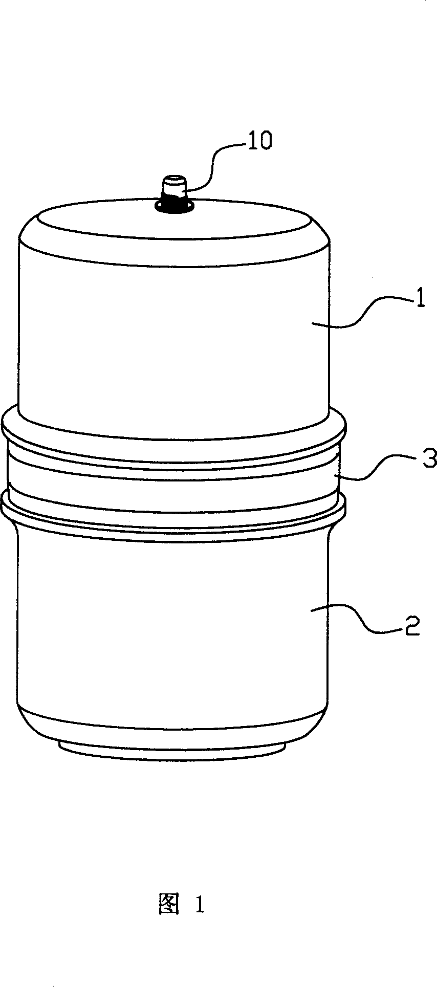
Figure 1 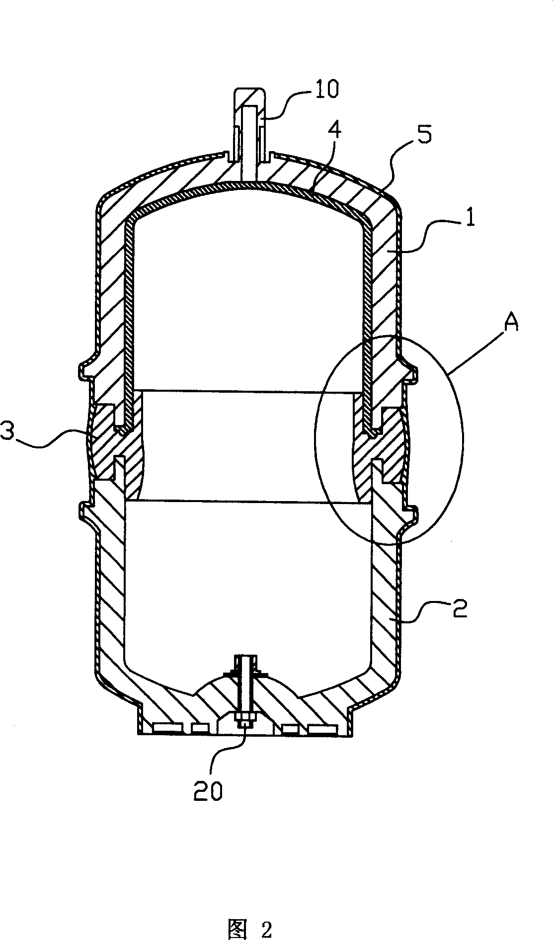
Figure 2 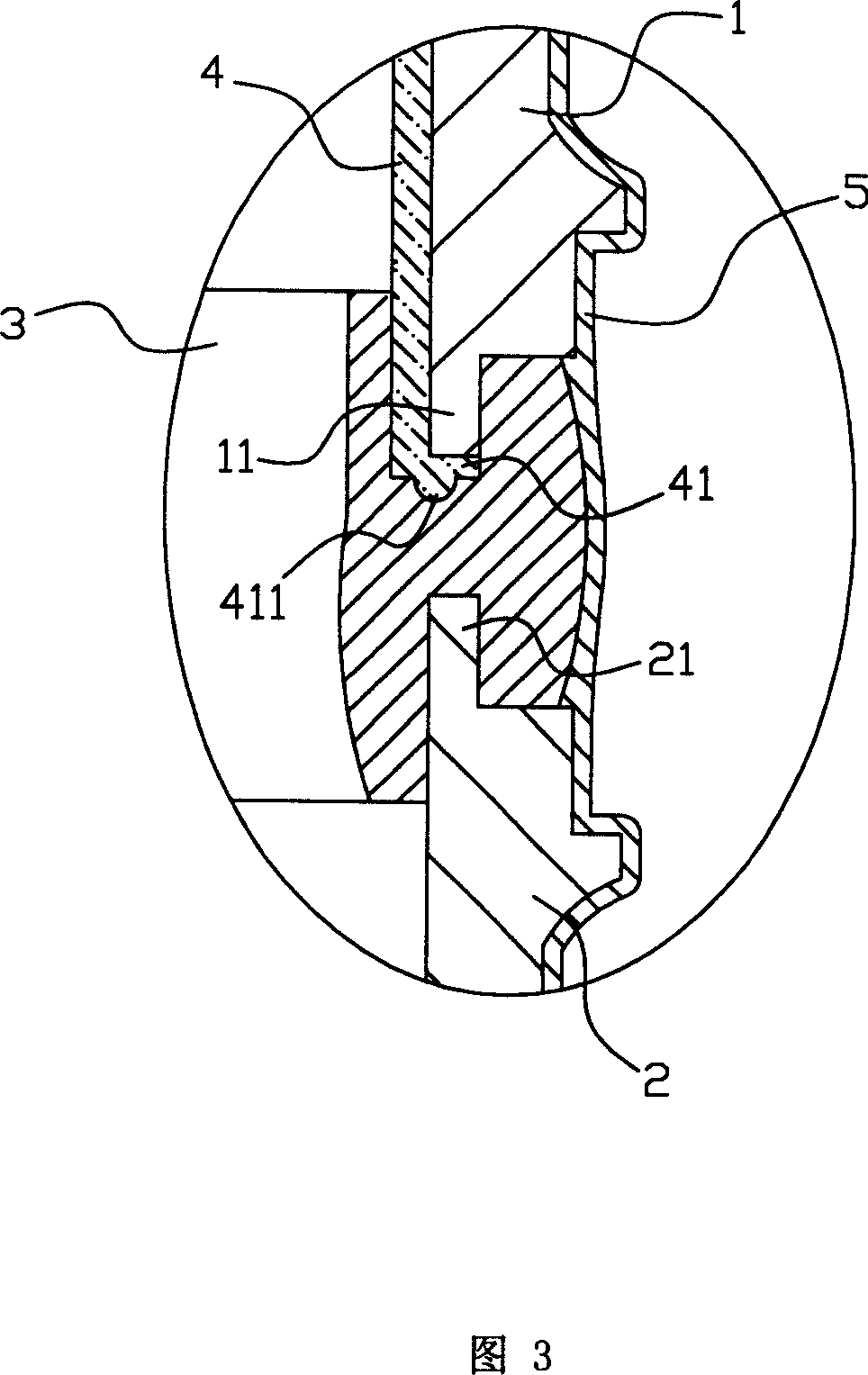
Figure 3
Abstract
Description
technical field
[0001] The invention relates to an auxiliary part of water purification equipment and its production process, in particular to a pressure barrel used for water purification equipment and its production process. Background technique
[0002] Water purification equipment that uses membrane methods to purify water has been more and more widely used. The main part of this kind of water purification equipment is a membrane tube with a membrane module, and a pre-filter device is provided before the membrane tube, and the water to be purified is pretreated by the pre-filter device before entering the membrane tube for reverse Osmotic treatment.
[0003] The membrane tube is usually connected with a pressure barrel, the pressure barrel is formed by the upper half barrel and the lower half barrel open facing butt joint, the upper half barrel is connected with the membrane module through a pipeline, the switch valve is arranged on the pipeline, and the lower half barr...
Examples
Embodiment Construction
[0020] A specific embodiment of the present invention will be described below with reference to FIGS. 1 to 4 .
[0021] Referring to Fig. 1, the pressure barrel used for water purification equipment in this embodiment includes an upper half barrel body 1 and a lower half barrel body 2 with openings docked with each other, and the upper half barrel body 1 and the lower half barrel body 2 are connected by a ring The part 3 is connected, and the top of the upper half barrel body 1 is provided with a water inlet and outlet 10 .
[0022] Referring to Fig. 2 to Fig. 4, the upper end surface of the annular connector 3 is provided with an annular groove 31 in which the periphery of the upper half barrel body 1 can be embedded, and the lower end surface is provided with an annular groove 32 in which the periphery of the lower half barrel body 2 can be embedded. . A stepped surface is formed on the outer side of the bottom periphery of the upper half barrel body 1, and the smaller part...