
Cutting mechanism of soft material product
A cutting mechanism and soft material technology, applied in metal processing and other directions, can solve the problems of increased frictional resistance, loss of kinetic energy of the cutting blade, easy rolling of cutting tools, etc., to reduce frictional resistance, reduce kinetic energy loss, and ensure the effect of cutting quality.
Patent Information
- Authority / Receiving Office
- CN · China
- Patent Type
- Applications(China)
- Current Assignee / Owner
- Publication Date
- 2010-08-18
- Estimated Expiration
- Not applicable · inactive patent
Smart Images
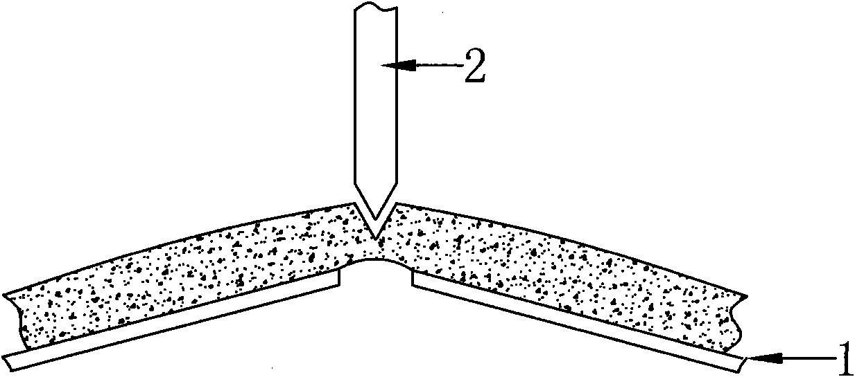
Figure 1 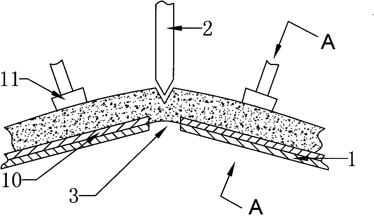
Figure 2 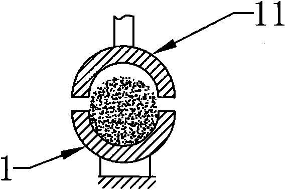
Figure 3
Abstract
Description
Technical field:
[0001] The invention relates to the technical field of cutting machinery, in particular to a cutting mechanism for soft material products such as leather, cloth, paper and sponge. Background technique:
[0002] Most of the existing cutting devices for soft material cutting are simply designed with a cutting table placed in a horizontal line. When the cutting knife is cutting, the width of the kerf cut by the blade of the cutting knife and the soft material product must be smaller than the width of the cutting knife blade. In this way, there will be mutual extrusion between the cutting knife and the soft material products on both sides of the slit. On the one hand, the friction resistance of the cutting knife will increase during the cutting process, resulting in loss of kinetic energy driving the cutting knife, increasing The energy consumption of the entire cutting device is increased because the cutting knives are generally driven by motors; and it is diff...
Examples
Embodiment 1
[0030] See attached figure 1 to attach Figure 4 , it includes a holder 1 and a cutting knife 2 described in this embodiment, wherein a cutting groove 3 for matching the cutting knife 2 is provided on the holder 1, and the cutting groove 3 on the holder 1 is formed For the arched structure, the cutting knife 2 is located in the arching direction of the arched structure. The holder 1 is provided with a groove 10 for accommodating the soft material to be cut, and the notch of the groove 10 is provided with a presser 11, and the notch in the presser 11 corresponds to the notch of the groove 10. Cooperate. After adopting the groove 10, the soft material product can be limited in the groove 10 for cutting, so as to ensure the smoothness of the incision after the soft material product is cut, and the phenomenon that the soft material product will not be displaced during the cutting process will affect the cutting process. product quality. The upwardly arched structure at the cut...
Embodiment 2
[0032] See attached Figure 5 The difference between the solution of this embodiment and the first embodiment is that the padding workpiece 4 is a square workpiece.
Embodiment 3
[0034] See attached Figure 6 The difference between the solution of this embodiment and the first embodiment is that the padding workpiece 4 is a circular workpiece, and the circular workpiece can be directly welded on the holder 1 or a concave hole is provided on the holder 1 to Positions circular workpieces.