
Injection apparatus in cold chamber die casting molding machine and measuring method used therein
a technology of injection apparatus and cold chamber die casting molding machine, which is applied in the direction of molten metal supply equipment, chemistry apparatus and processes, manufacturing tools, etc., can solve the problems of high running cost, large volume, and long time required to raise or lower the furnace temperature, and achieve accurate measurement control
Patent Information
- Authority / Receiving Office
- US · United States
- Patent Type
- Applications(United States)
- Current Assignee / Owner
- Publication Date
- 2006-03-02
Smart Images
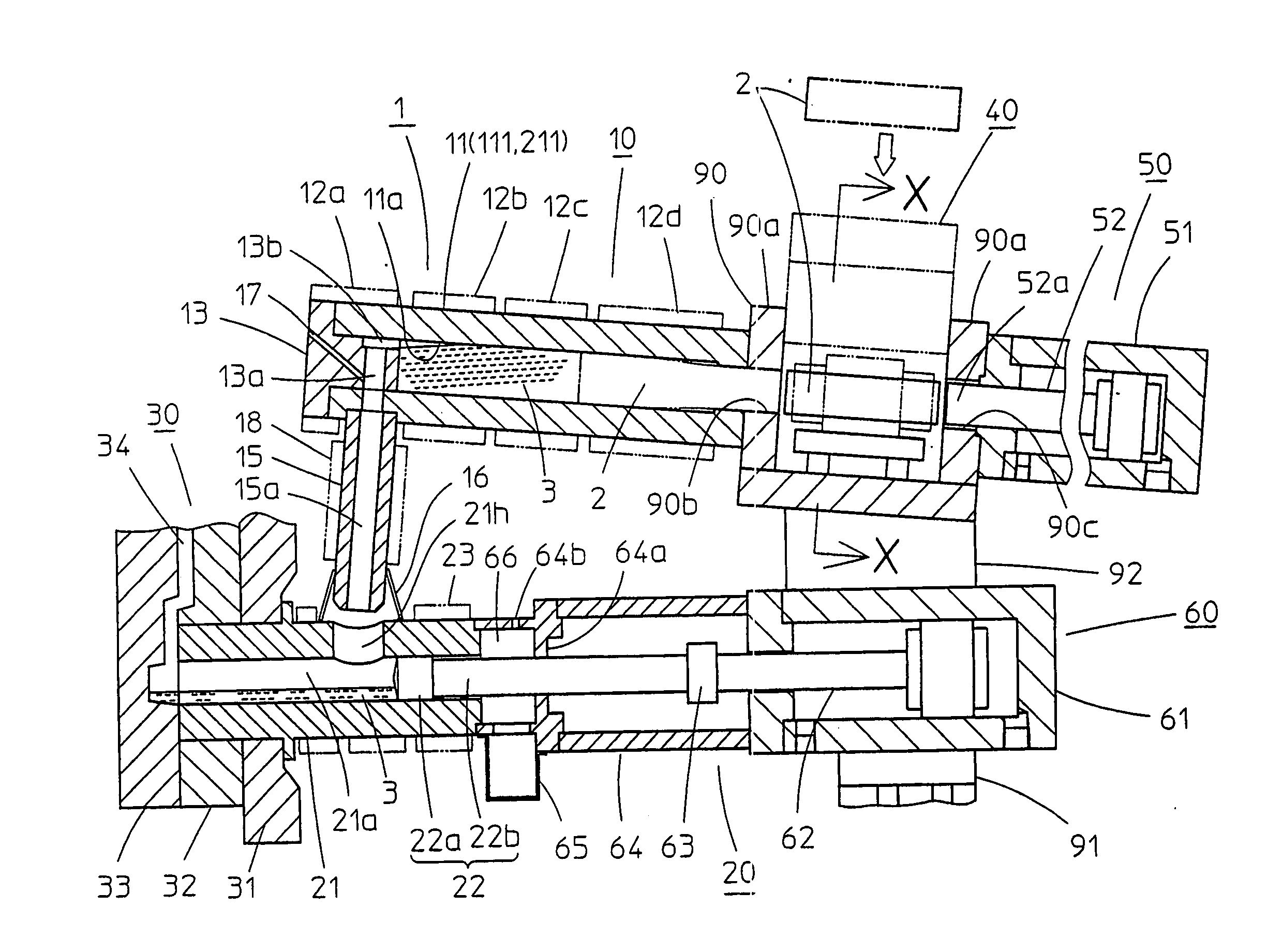
Figure 1 
Figure 2 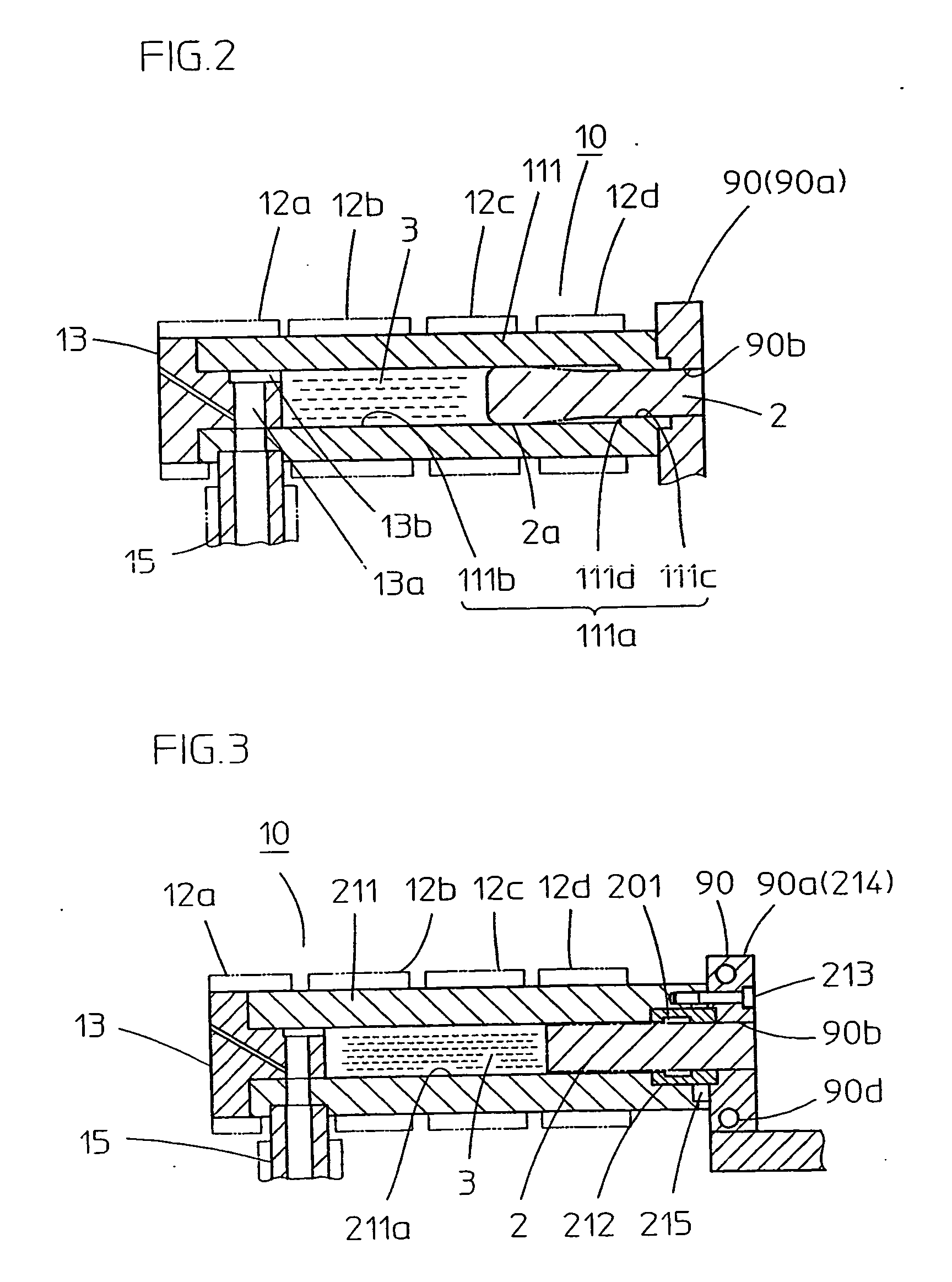
Figure 3
Abstract
Description
TECHNICAL FIELD
[0001] This invention relates to an injection apparatus in a cold chamber die casting molding machine. More specifically, this invention relates to an injection apparatus, which replenishes light metal material into its melting device in the form of a billet such as a short cylindrical rod for melting and supplies the molten metal into a plunger injection device for measuring. Moreover, this invention relates to measuring method for the cold chamber die casting molding machine. BACKGROUND ART
[0002] An injection molding machine for light metal alloys such as magnesium, aluminum, zinc is generally called a die casting molding machine, and is classified into a hot chamber method machine and a cold chamber method machine. The former hot chamber machine, in which an injection device is provided on a furnace, measures one shot of the molten metal in an injection sleeve of the injection device by sucking the molten metal from the furnace, and injects it into a mold cavity ...
Examples
first embodiment
[0048] Reference numeral 111 in FIG. 2 denotes the first melting cylinder of the Most of a cylinder bore 111a of this cylinder 111 except for the vicinity of the base end is formed to have a few mm larger diameter than the billet 2 and the base end of this cylinder bore 111a has a slightly larger diameter than the billet 2. Between them, a stepped section 111d is formed. In case this melting cylinder is for melting magnesium alloy, the gap of a larger diameter cylinder bore 111b with regard to the billet 2 is formed to secure about 1 mm to 2 mm. Also the gap of a base end side of the cylinder bore 111c with the billet 2 which has expanded thermally slightly, is formed to secure about 0.2 mm to 0.5 mm. The position of the stepped section 111d is formed beforehand at an appropriate position in accordance with some conditions, such as the inside diameter of the melting cylinder 111, the volume of molten metal 3, temperature setting of the heater band 12c, 12d, or the gap of the larger...
second embodiment
[0049] Reference numeral 211 in FIG. 3 denotes a second melting cylinder of the This melting cylinder 211 is combined with its base end to the side plate 90a of the central frame member 90 by bolts 213 along with a cooling sleeve 212 which is described later. In this embodiment, a cooling duct 90d for circulating cooling fluid is formed at the periphery of the through hole 90b of the side plate 90a. Therefore the side plate 90a functions as a cooling member and hence is also called a cooling member 214 in the following description. As a matter of course, this cooling member 214 may be composed as the different part from the side plate 90a and may be arranged at any place as long as it is furnished between melting cylinder 211 and the side plate 90a. In case the billet 2 is magnesium alloy the gap between the through hole 90b and the billet 2 is formed to secure about 0.2 mm to 0.5 mm when the billet 2 has expanded thermally slightly. Owing to this gap in the through hole 90b and th...