
Defoaming device of plate type falling film evaporator
A falling film evaporator, plate-type technology, applied in evaporator accessories, evaporation, chemical instruments and methods, etc., can solve the problems of unreasonable baffle design, poor defoaming effect, increased production costs, etc., and achieve improved defoaming Foaming effect, reduce production cost, improve defoaming efficiency and quality
Patent Information
- Authority / Receiving Office
- CN · China
- Patent Type
- Applications(China)
- Current Assignee / Owner
- Publication Date
- 2011-04-06
- Estimated Expiration
- Not applicable · inactive patent
Smart Images
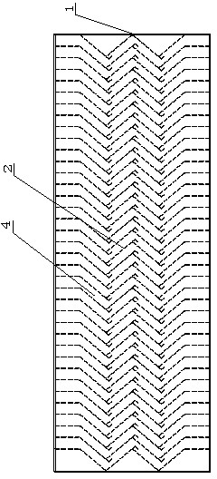
Figure 1 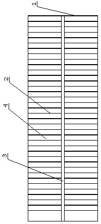
Figure 2 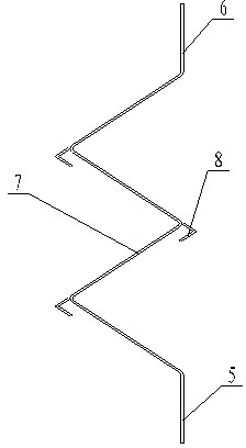
Figure 3
Abstract
Description
technical field
[0001] The invention relates to a plate type falling film evaporator, in particular to a demister of the plate type falling film evaporator. Background technique
[0002] Plate falling film evaporator is widely used in papermaking, chemical industry and other fields. Among them, the defoaming device is a device used in the plate falling film evaporator to separate the secondary steam and improve the cleanliness of the condensed water of the secondary steam. The defoaming device of the plate type falling film evaporator is generally installed in the separation chamber of the lower half of the shell of the plate evaporator, and is located between the shell and the heat exchange plate. The defoaming device divides the separation chamber into upper and lower parts. A secondary steam outlet is opened on the shell wall of the upper part of the chamber. The defoaming device is generally composed of an outer protective frame, a number of baffle damping blades arran...
Examples
Embodiment Construction
[0013] Specific embodiments of the present invention will be described in detail below in conjunction with the accompanying drawings.
[0014] Such as figure 1 , figure 2 As shown, the defoaming device of the plate type falling film evaporator includes an outer protective frame 1, a number of parallel baffle damping blades 2 arranged in the outer protective frame 1, and a reinforcing plate for fixing a plurality of baffle damping blades 2 3. The defoaming channel 4 is formed between the baffle damping vanes 2, and the baffle damping vanes 2 are bent into an inlet section 5, an outlet section 6, and several times of bending between the inlet section 5 and the outlet section 6 The bent section 7 is formed, the outer corner of the bent section 7 is provided with an L-shaped fin 8 for hindering the steam flow direction, and the baffle damping blade 2 between the inlet section 5 and the outlet section 6 is folded three times. Bend to form a W-shaped bending section 7, and the an...