
Money sending mechanism and self-service deposit and withdrawal device thereof
A banknote feeding and equipment technology, applied in the direction of handling coins or valuable banknotes, coin accepting devices, instruments, etc., can solve problems such as increased running resistance of the banknote pushing plate, failure of deposit and withdrawal services, banknote inclination, etc. Achieve the effects of stable and reliable structure, high power transmission efficiency and avoiding errors
Patent Information
- Authority / Receiving Office
- CN · China
- Current Assignee / Owner
- Publication Date
- 2015-04-22
Smart Images
Figure 1 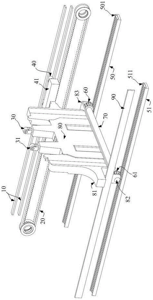
Figure 2
Abstract
Description
technical field
[0001] The invention belongs to the technical field of self-service deposit and withdrawal equipment, and in particular relates to a banknote feeding mechanism and a self-service deposit and withdrawal equipment. Background technique
[0002] ATM (Automatic Teller Machine, automatic teller machine) is a highly sophisticated electromechanical integration device that uses magnetic code cards or smart cards to realize self-service financial transactions, replacing the work of bank counter staff. Cardholders can use the credit card or savings card based on the set password to realize cash withdrawal, balance inquiry, fund transfer and other services based on the ATM. related work.
[0003] As the mainstream business of ATM equipment, the deposit and withdrawal service is currently widely used to transport cash and banknotes through the banknote push plate. For different ATM manufacturers, the banknote delivery mechanisms are also designed in different ways. F...
Examples
Embodiment 1
[0047] refer to figure 2 As shown, a banknote feeding mechanism provided in this embodiment includes guide racks (50, 51), gears (60, 61), bearing shaft 70, banknote pushing plate 80, synchronous drive belt 20, and limit guide groove 10 And travel stabilizing member 41.
[0048] In this embodiment, the guide racks (50, 51) are two parallel racks.
[0049] In this embodiment, the bearing shaft 70 is arranged substantially perpendicular to the guide racks ( 50 , 51 ), and the gears ( 60 , 61 ) are fixed at two opposite ends of the bearing shaft 70 . There are two bearing shafts 70 and are respectively engaged with the guide racks (50, 51) one by one. The gears ( 60 , 61 ) are rigidly connected to the bearing shaft 70 . In a preferred embodiment, the gears ( 60 , 61 ) are in one-to-one correspondence with the guide racks ( 50 , 51 ), and the gears ( 60 , 61 ) cannot rotate relative to the bearing shaft 70 .
[0050]In this embodiment, the first plane where the banknote pushi...
Embodiment 2
[0061] continue to refer figure 2 , this embodiment only describes the difference from the above-mentioned embodiment 1, the difference is: in this embodiment, the gears (60, 61) are bearing-connected to the bearing shaft 70; the banknote pushing plate 80 is rigidly connected to the bearing shaft 70 . The gears (60, 61) are connected to both ends of the bearing shaft 70 through bearings, the gears (60, 61) can rotate around the bearing shaft 70, and the bearing shaft 70 is rigidly connected to the Above the banknote pushing plate 80.
[0062] Correspondingly, this embodiment also provides a self-service deposit and withdrawal device, which includes the banknote feeding mechanism described in this embodiment.