
Oily wastewater recycling and wastewater treatment system and treatment method thereof
A wastewater treatment system and resource utilization technology, applied in water/sewage treatment, chemical instruments and methods, water/sewage multi-stage treatment, etc., can solve problems such as difficult and effective oil-water separation and resource utilization, and achieve energy and resource utilization to ensure the effect of stable operation
Patent Information
- Authority / Receiving Office
- CN · China
- Patent Type
- Applications(China)
- Current Assignee / Owner
- Publication Date
- 2016-06-08
- Estimated Expiration
- Not applicable · inactive patent
Smart Images
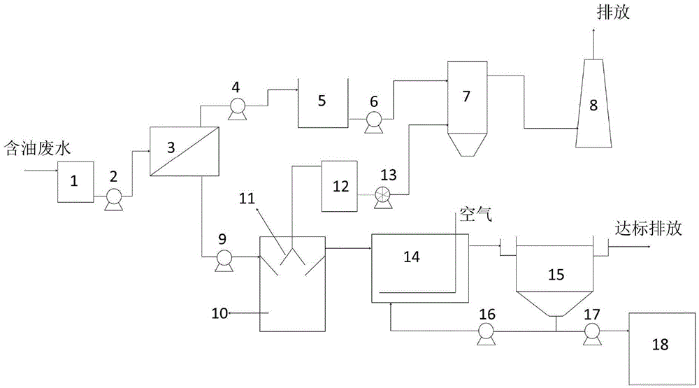
Figure 1
Abstract
Description
technical field
[0001] The invention belongs to the field of oily wastewater treatment, and in particular relates to an oily wastewater recycling and wastewater treatment system and a treatment method thereof. Background technique
[0002] Oily wastewater comes from a wide range of sources, mainly including: oilfield wastewater, petrochemical wastewater, food processing wastewater, metal cutting fluid wastewater, and tannery wastewater. These industries are the largest water consumers in my country and also the largest pollutant dischargers in my country. With the increasing environmental pollution and the increasing shortage of water resources, it is urgent to treat this type of wastewater. According to the form of oil distribution in water, oily wastewater can be divided into four types: floating oil, dispersed oil, emulsified oil and dissolved oil.
[0003] At present, common traditional oily wastewater treatment technologies include: centrifugation, oil separation, air...
Examples
Embodiment 1
[0033] Such as figure 1 As shown, an oily wastewater recycling and wastewater treatment system in this embodiment includes a raw water conditioning tank 1, an ultrafiltration separation unit 3, an oil storage tank 5, an incinerator 7, a flue gas discharge tower 8, and a biogas storage tank 12 , anaerobic reactor 10, three-phase separator 11, aerobic reactor 14, sedimentation tank 15, sludge thickening tank 18; described raw water adjustment tank 1 and ultrafiltration separation unit 3 pass waste water delivery pump 2 and pipeline Connected, the ultrafiltration separation unit 3 and the oil storage tank 5 are connected to each other through the membrane dope delivery pump 4 and the pipeline, and the oil storage tank 5 and the incinerator 7 are connected to each other through the incinerator oil delivery pump 6 and the pipeline, so Described incinerator 7 is connected with flue gas discharge tower 8 by pipeline; Described ultrafiltration separation unit 3 and anaerobic reactor 1...
Embodiment 2
[0037] The basic structure is the same as in Example 1, wherein the ultrafiltration membrane used in the ultrafiltration separation unit 3 is an organic-inorganic composite ultrafiltration membrane, and the membrane has good oil-water separation performance. The membrane is backwashed regularly, and the backwash water flows into the Raw water adjustment pool 1.
Embodiment 3
[0039] The basic structure is the same as in Embodiment 1, wherein the pumps used in the ultrafiltration separation unit 3 to the incinerator 7 are anti-stick screw pumps or gear pumps.