
A rubber bushing type engine mount
An engine mount, rubber bushing technology, applied in power plant, jet propulsion, internal combustion propulsion and other directions, can solve the problems of large tensile displacement, reduced fatigue reliability of rubber main spring, increased cost, etc., to improve fatigue characteristics, reduced quality instability, cost-saving effects
Patent Information
- Authority / Receiving Office
- CN · China
- Patent Type
- Patents(China)
- Current Assignee / Owner
- Publication Date
- 2017-11-28
Smart Images
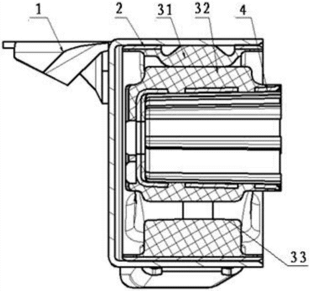
Figure 1 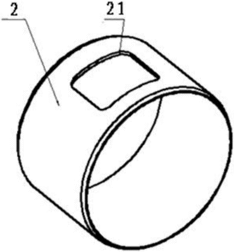
Figure 2 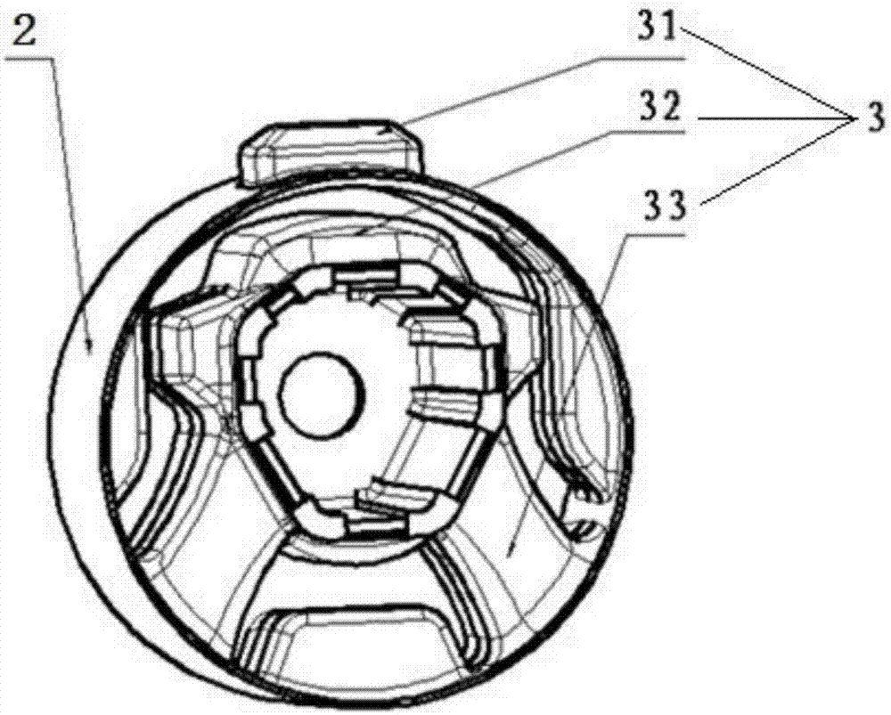
Figure 3
Abstract
Description
Technical field
[0001] The present invention relates to engine accessories, in particular to a rubber bushing type engine suspension with pre-compression function. Background technique
[0002] Engine mount refers to the elastic body connected between the powertrain and the car body. It has the functions of support, limit and vibration reduction. It is the most important vibration isolation element. The advantages and disadvantages of its structure have a great effect on the smoothness of the car. Impact. The main structural forms of engine mounts include the following three types: one is compression type, which is rubber vulcanization on the upper and lower sheet metal. The compression type suspension has relatively small volume, relatively simple structure, and large compression stiffness, but the shear The stiffness is low. The other is the shear type, where the rubber is vulcanized to the casing and mainly bears the shearing force. The shear type suspension can provide grea...
Examples
Embodiment Construction
[0018] The present invention will be further described in detail below in conjunction with the drawings and embodiments.
[0019] See figure 1 , figure 2 , image 3 with Figure 4 The shown engine suspension with rubber bushings includes a bracket 1 with a sleeve and a rubber bushing assembly matched with the sleeve on the bracket. The prominent substantive features are:
[0020] The rubber bushing assembly is composed of an outer sleeve 2, an inner sleeve 4, and a vulcanized rubber member 3 arranged between the outer sleeve and the inner sleeve. The outer sleeve is provided with a square hole 21; the vulcanized rubber member 3 includes The upper limit structure 31 connected with the outer rubber ring, the lower limit structure 32 connected with the inner rubber ring, the outer rubber ring is in close contact with the inner wall of the outer sleeve 2, and the inner rubber ring is sleeved on the inner sleeve The outer wall of the tube 4; the upper limit structure is a square boss ...