
A rotor structure, permanent magnet synchronous motor and compressor
A permanent magnet synchronous motor and rotor structure technology, applied in the direction of magnetic circuit shape/style/structure, magnetic circuit, electromechanical device, etc., can solve the problems of difficult to increase the working efficiency of the magnetic steel flux linkage motor and the high manufacturing cost of the motor, and achieve Effects of improving flux linkage and work efficiency, improving work efficiency, and reducing usage
Patent Information
- Authority / Receiving Office
- CN · China
- Patent Type
- Patents(China)
- Current Assignee / Owner
- Publication Date
- 2018-12-28
Smart Images
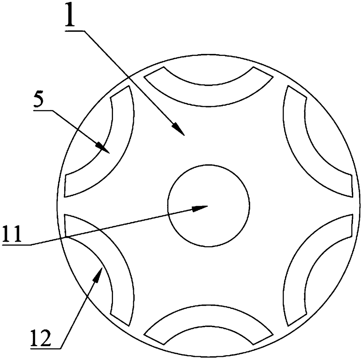
Figure 1 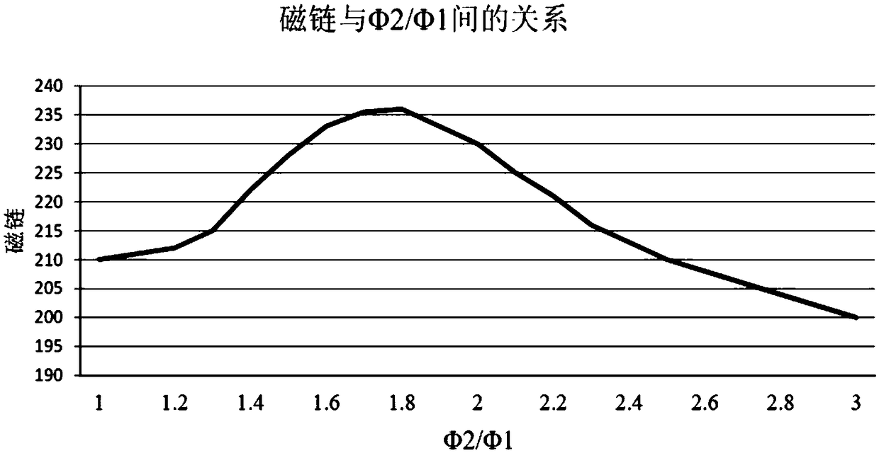
Figure 2 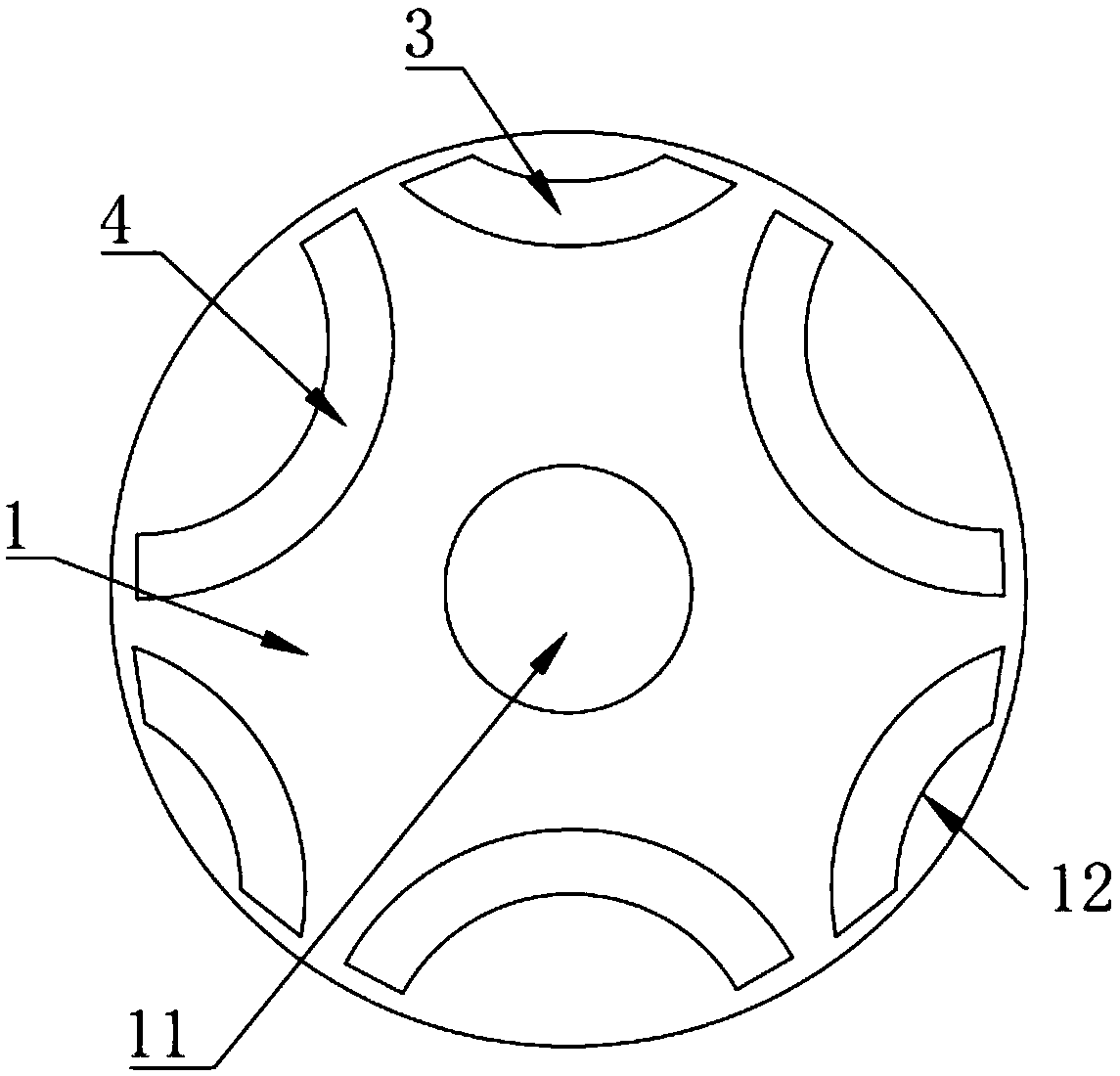
Figure 3
Abstract
Description
technical field
[0001] The invention belongs to the technical field of motors, and in particular relates to a rotor structure, a permanent magnet synchronous motor and a compressor. Background technique
[0002] The permanent magnet synchronous motor uses the electromotive force generated by the electromagnetic induction between the stator and the rotor to drive the load. With the rapid development of power electronics technology, microelectronics technology, new motor control theory and rare earth permanent magnet materials, the permanent magnet synchronous motor can be rapidly developed. Promote apps. For example, it is used in servo system, electric traction and other occasions.
[0003] The structure of the rotor in the permanent magnet synchronous motor in the prior art is as follows figure 1 As shown, the rotor core 1 is included, and an even number of magnetic steel slots 12 are opened along its axial direction, and the magnetic steels 5 installed in the magnetic st...
Examples
Embodiment 1
[0046] This embodiment provides a rotor structure, such as image 3 As shown, it includes a rotor core 1 , a first magnet 3 and a second magnet 4 . Among them, the rotor core 1 has an inner hole 11 and six magnetic steel grooves 12 along its axial direction, and the six magnetic steel grooves 12 are symmetrically distributed around the outer circumference of the inner hole 11 in the rotor core 1; the first magnetic steel 3 Installed in the magnetic steel slot 12 at intervals with the second magnetic steel 4, the polarity of the first magnetic steel 3 is opposite to that of the adjacent second magnetic steel 4, and the first magnetic steel 3 and the second magnetic steel 4 adopt Made of the same material, for example, all adopt NdFeB, or ferrite, or other magnetic materials, the length of the first magnet 3 is less than the length of the second magnet 4, so that the magnetic flux of the second magnet 4 The ratio to the magnetic flux of the first magnet 3 is within a range grea...
Embodiment 2
[0057] This embodiment provides a rotor structure, such as Figure 6 , the difference from the rotor structure provided in Example 1 is only that the volume of the first magnet 3 is the same as that of the second magnet 4, the first magnet 3 is made of low grade magnets, and the second magnet 4 is made of high Brand of magnetic steel.
[0058] In this embodiment, by changing the grade of the magnets, the single-piece magnetic flux value is changed, so that the first magnets 3 under a pair of poles adopt low-grade magnets, and the residual magnetism of the low-grade magnets is small, and the first magnets 3 The magnetic flux of the second magnet 4 is reduced, and the second magnet 4 adopts a high-grade magnet, and its residual magnetism is large, so the magnetic flux of the second magnet 4 is increased, so that the ratio of the magnetic flux of the second magnet 4 to the magnetic flux of the first magnet 3 In the range of greater than 1 and less than 2.5, compared with the tra...
Embodiment 3
[0064] A permanent magnet synchronous motor provided in this embodiment includes a rotor structure, and the rotor structure is any one of the rotor structures provided in Embodiment 1 or Embodiment 2. The permanent magnet synchronous motor in this embodiment adopts the rotor structure in Embodiment 1 or Embodiment 2, so that the working point of the motor moves up, and the flux linkage of the motor is increased. When driving the same load, the rotor excitation field is more Larger, the smaller the stator armature current required, the smaller the stator copper loss, thereby improving the working efficiency of the motor; at the same time, reducing the use of magnetic steel and reducing the manufacturing cost of the motor.