
Three-layer electric dining table
An electric dining table, round table technology, applied in the direction of tables, service tables, legs of general furniture, etc., can solve problems such as easy failure, and achieve the effects of improving safety, increasing electrical conductivity, and achieving cleanliness and maintenance.
Patent Information
- Authority / Receiving Office
- CN · China
- Patent Type
- Applications(China)
- Current Assignee / Owner
- Publication Date
- 2017-05-31
- Estimated Expiration
- Not applicable · inactive patent
Smart Images
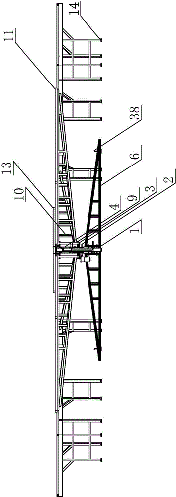
Figure 1 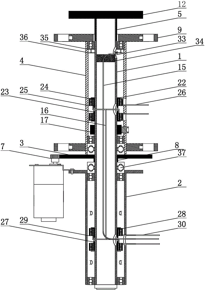
Figure 2 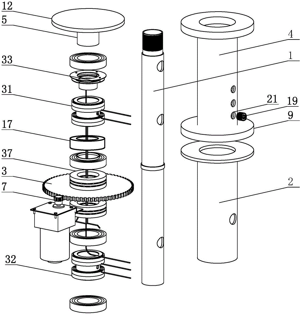
Figure 3
Abstract
Description
technical field
[0001] The invention relates to the field of automatic table equipment, in particular to a three-layer electric table. Background technique
[0002] In large banquets, it is often necessary to use multi-layer rotating tables. The existing large revolving dining tables are often prone to failures during use due to the huge device and heavy desktop. The main reasons are as follows:
[0003] Due to the large size of the large dining table, in order to facilitate the table setting, it is often necessary to set up a three-layer structure. Due to the need to stop and start the rotation from time to time during the meal and table setting, and the different requirements for the rotation of different items placed on each layer, multi-layer The high-quality rotating table puts forward higher requirements for the rotating structure. However, the rotating table of the prior art has deficiencies in the design of the rotation control and the rotating structure, and is pr...
Examples
Embodiment
[0046] Embodiment: The present invention is a three-layer electric dining table. The main structure includes a shaft core 1 arranged in the center. The shaft core 1 is provided with a lower sleeve 2, a large gear plate 3, and an upper sleeve 4 in sequence from bottom to top. . Threaded sleeve 5, the top and bottom of the lower sleeve 2 are provided with second bearings, and the lower sleeve 2 is rotationally connected with the shaft core 1 through the second bearings. The outer wall of the lower sleeve 2 is fixed with a triangular floor stand 6, and the lower sleeve 2 is fixed with a motor, and the motor is provided with a drive gear 7, and the large gear plate 3 is installed in the middle of the shaft core 1. on the bearing position 8, and the large gear plate 3 is meshed with the drive gear 7, a plane bearing 37 is installed between the large gear plate 3 and the upper sleeve 4, and a plane bearing 37 is installed between the bearing position 8 and the lower sleeve 2 Plane b...