
Beam and pillar node dry connection fan-shaped viscoelastic damper
A technology of beam-column joints and dry connections, which is applied in the direction of building components, building structures, building types, etc., can solve the performance fluctuation of viscoelastic dampers, occupy a large space, and lead viscoelastic sector dampers do not have the ability to withstand beam shear. issues of strength
Patent Information
- Authority / Receiving Office
- CN · China
- Patent Type
- Applications(China)
- Current Assignee / Owner
- Publication Date
- 2017-05-31
Smart Images
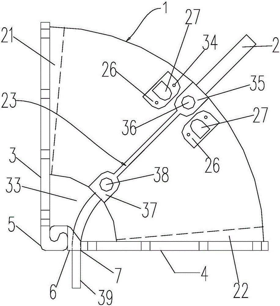
Figure 1 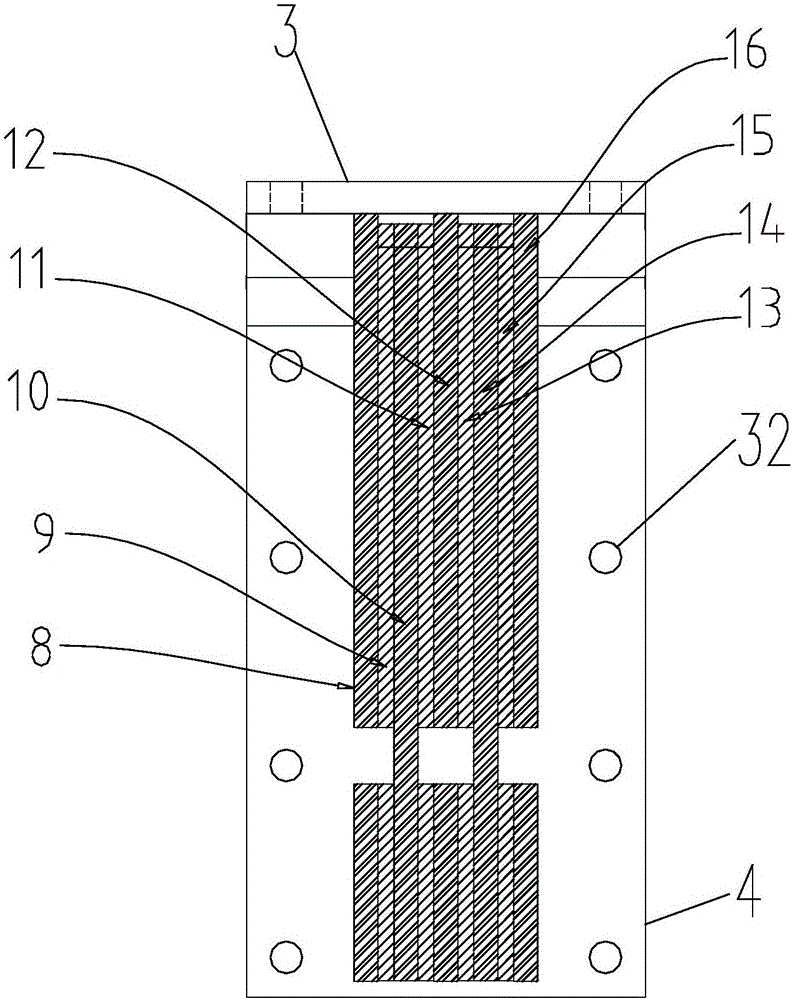
Figure 2 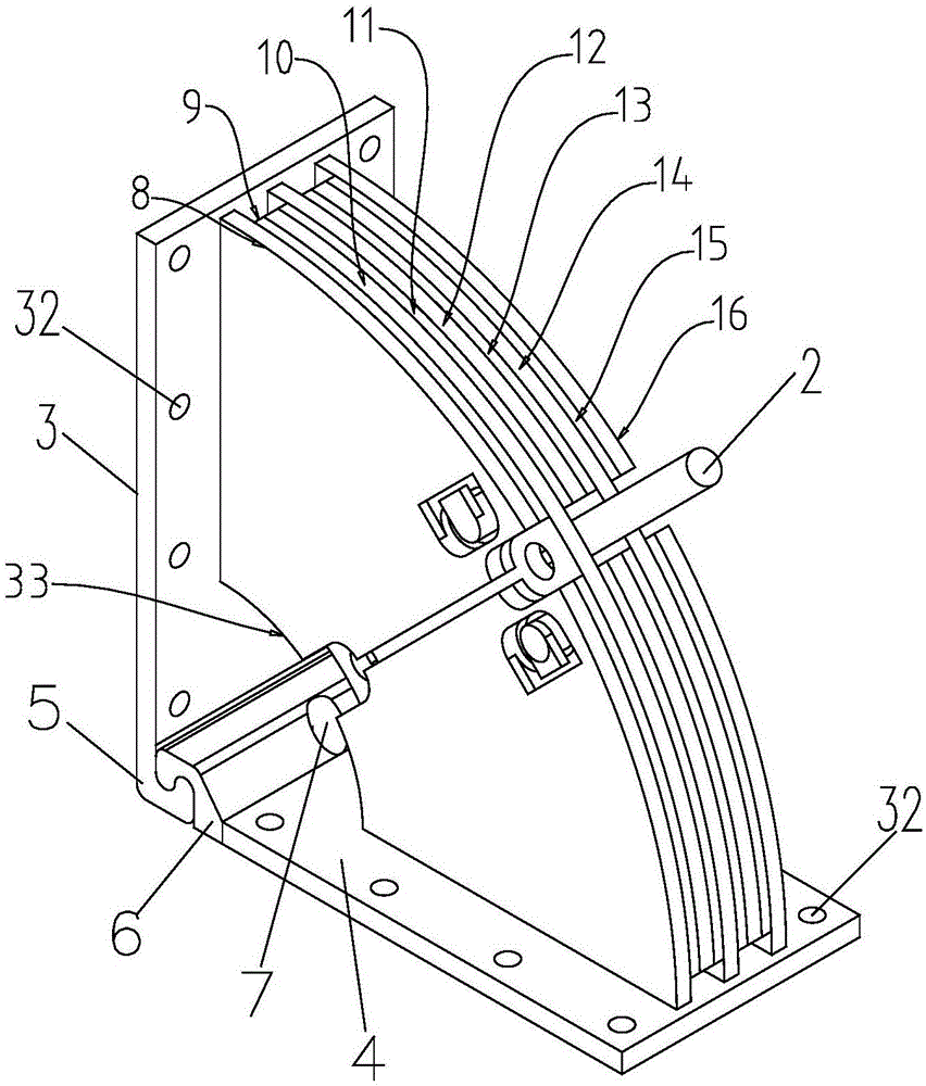
Figure 3
Abstract
Description
technical field
[0001] The invention belongs to the field of engineering structures, and relates to building components for beam-column joint connection, position limitation and shock absorption, in particular to a sector-shaped viscoelastic damper for beam-column joint dry connection. Background technique
[0002] Under the action of earthquakes, the frame structure must meet the "strong earthquake resistance" and the frame structure must provide sufficient deformation capacity under the action of wind load. The frame must have good energy dissipation capacity and deformation capacity. The traditional frame structure relies on the consumption of the structure itself. Energy and provide deformation, limited ability. A reasonable and effective anti-seismic approach is to install anti-seismic devices on the structure, and the anti-seismic devices and the structure jointly bear the seismic action, that is, jointly store and dissipate seismic energy, so as to reduce and adjust t...
Examples
Embodiment Construction
[0035] Attached below Figures 1 to 16 The present invention is further described.
[0036]Solution 1 of the present invention provides a sector-shaped viscoelastic damper for beam-column joint stem connection, which includes a composite energy-dissipating support body 1, a beam connecting plate 3, a column connecting plate 4 and a position-limiting device, the lower end of the beam connecting plate 3 and the column The left end of the connecting plate 4 has an upright U-shaped groove part one 5 and an inverted U-shaped groove part two 6 respectively, and the left side wall of the U-shaped groove part two 6 is snap-fittingly arranged In the notch, the cooperation between the U-shaped groove part one 5 and the U-shaped groove part two 6 makes the beam connection plate 3 and the column connection plate 4 have a rotation range of 80-100 degrees, that is, the beam connection plate 3 and the column connection plate The connecting plate 4 passes through the U-shaped groove part 1 5...