
A rapid screening device for concrete raw materials used in bridge guardrail pouring construction
A screening device and concrete technology, which is applied in the fields of filtration, solid separation, chemical instruments and methods, etc., can solve the problems of poor screening effect, cumbersome operation, time-consuming and laborious, etc.
Patent Information
- Authority / Receiving Office
- CN · China
- Patent Type
- Patents(China)
- Current Assignee / Owner
- Publication Date
- 2020-10-27
Smart Images
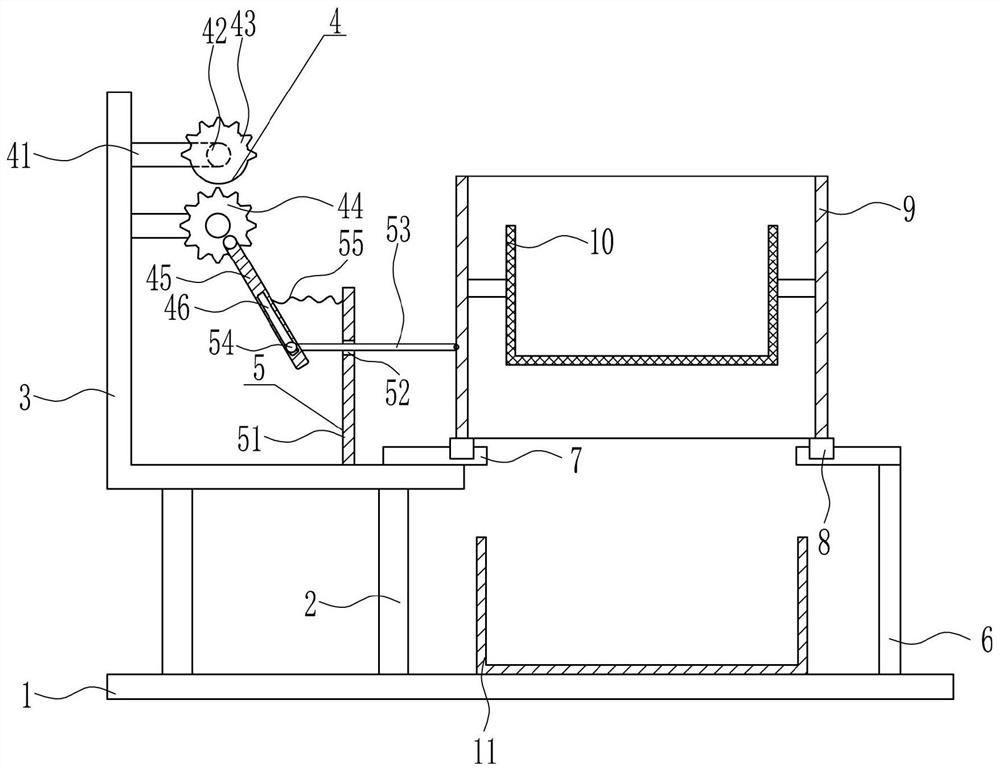
Figure 1 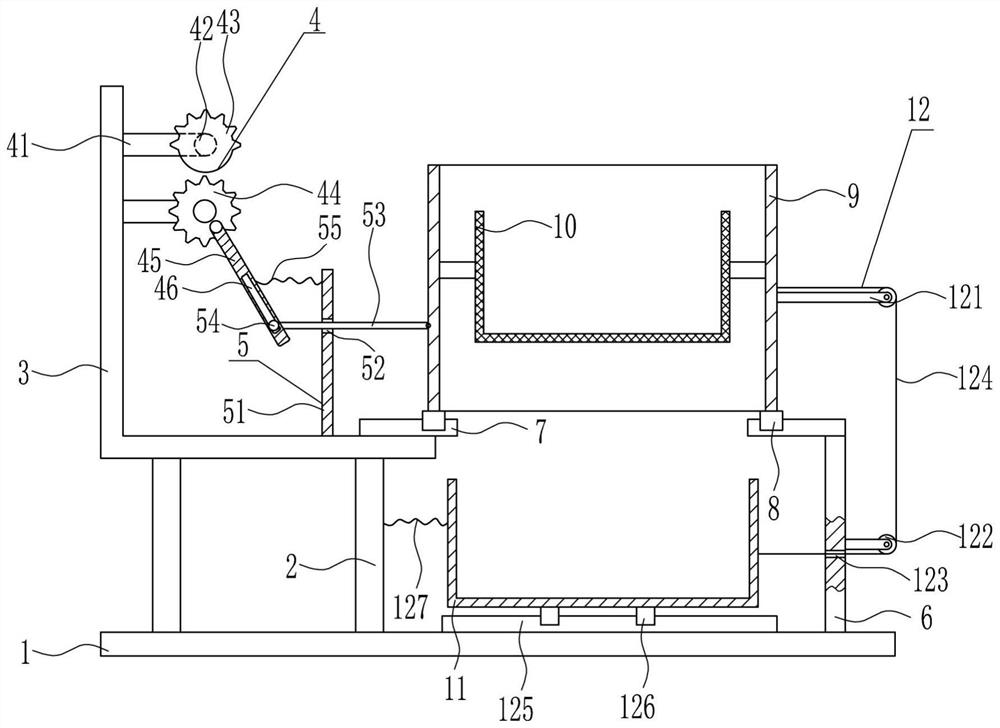
Figure 2 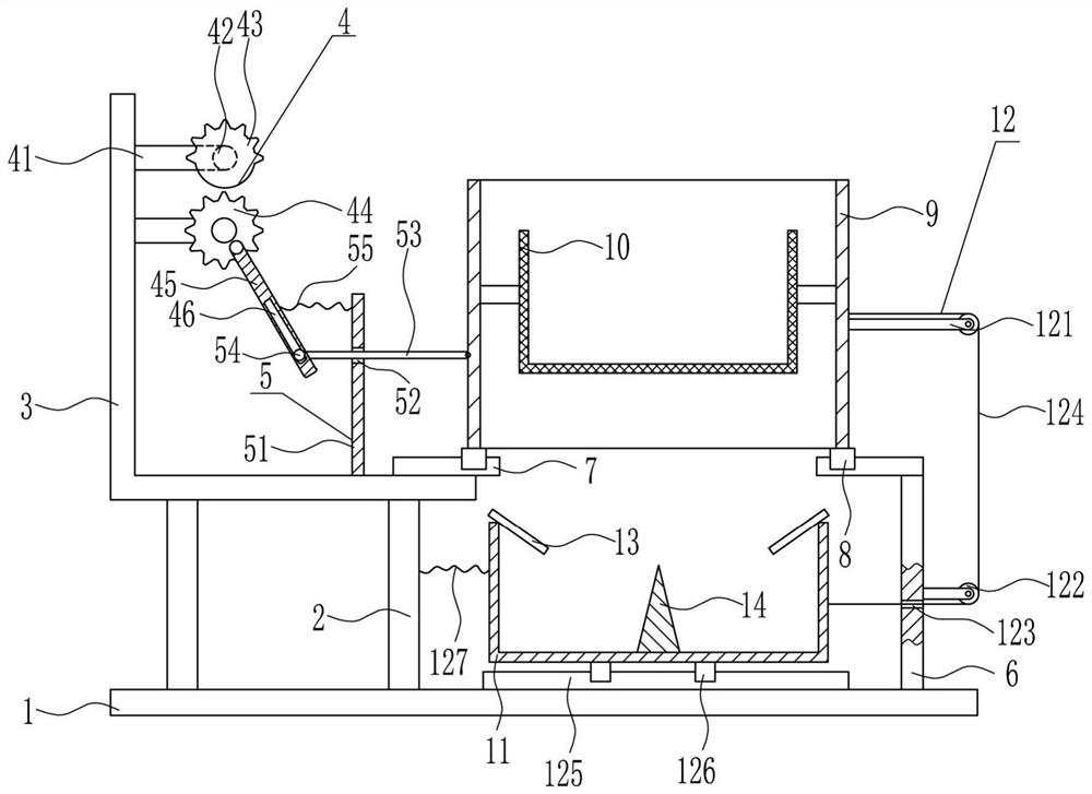
Figure 3
Abstract
Description
technical field
[0001] The invention belongs to the technical field of bridge pouring, in particular to a rapid screening device for concrete raw materials used in bridge guardrail pouring construction. Background technique
[0002] Bridges generally refer to structures erected on rivers, lakes and seas to allow vehicles and pedestrians to pass smoothly. In order to adapt to the modern high-speed development of the transportation industry, bridges are also extended to buildings that cross mountain streams, poor geology or meet other transportation needs to make traffic more convenient. A bridge is generally composed of a superstructure, a substructure, a support and ancillary structures. The superstructure is also called a bridge span structure, which is the main structure for crossing obstacles; the substructure includes abutments, piers and foundations; Or the force transmission device installed at the supporting place of the bridge abutment; the auxiliary structures refe...
Examples
Embodiment 1
[0026] A rapid screening device for concrete raw materials used in bridge guardrail pouring construction, such as Figure 1-3 As shown, it includes a base plate 1, a first bracket 2, an L-shaped support plate 3, a driving device 4, a first moving device 5, a second bracket 6, a first slide rail 7, a first slider 8, a frame body 9, The screening frame 10 and the collection frame 11, the top left side of the bottom plate 1 is vertically connected with the first support 2 by means of bolt connection, the top of the first support 2 is connected with the L-shaped support plate 3 by means of bolt connection, and the L-shaped support plate 3 The inner left side is provided with a driving device 4, the inner bottom of the L-shaped support plate 3 is provided with a first moving device 5, the right side of the top of the bottom plate 1 is connected with a second bracket 6 by means of bolt connection, and the right side of the first moving device 5 is The bottom of the inner side of the...
Embodiment 2
[0028] A rapid screening device for concrete raw materials used in bridge guardrail pouring construction, such as Figure 1-3As shown, it includes a base plate 1, a first bracket 2, an L-shaped support plate 3, a driving device 4, a first moving device 5, a second bracket 6, a first slide rail 7, a first slider 8, a frame body 9, The screening frame 10 and the collection frame 11, the top left side of the bottom plate 1 is vertically connected with the first support 2 by means of bolt connection, the top of the first support 2 is connected with the L-shaped support plate 3 by means of bolt connection, and the L-shaped support plate 3 The inner left side is provided with a driving device 4, the inner bottom of the L-shaped support plate 3 is provided with a first moving device 5, the right side of the top of the bottom plate 1 is connected with a second bracket 6 by means of bolt connection, and the right side of the first moving device 5 is The bottom of the inner side of the ...
Embodiment 3
[0031] A rapid screening device for concrete raw materials used in bridge guardrail pouring construction, such as Figure 1-3 As shown, it includes a base plate 1, a first bracket 2, an L-shaped support plate 3, a driving device 4, a first moving device 5, a second bracket 6, a first slide rail 7, a first slider 8, a frame body 9, The screening frame 10 and the collection frame 11, the top left side of the bottom plate 1 is vertically connected with the first support 2 by means of bolt connection, the top of the first support 2 is connected with the L-shaped support plate 3 by means of bolt connection, and the L-shaped support plate 3 The inner left side is provided with a driving device 4, the inner bottom of the L-shaped support plate 3 is provided with a first moving device 5, the right side of the top of the bottom plate 1 is connected with a second bracket 6 by means of bolt connection, and the right side of the first moving device 5 is The bottom of the inner side of the...