
Beidou pole-rod buoy antenna
A technology of Beidou pole and buoy, which is applied in the field of satellite navigation buoy antenna, can solve the problems of difficulty in ensuring the normal operation of the terminal, narrow beam of ceramic antenna, unfavorable light weight of equipment, etc., and achieve the effect of light weight, wide beam and low loss
Patent Information
- Authority / Receiving Office
- CN · China
- Current Assignee / Owner
- Publication Date
- 2017-12-01
Smart Images
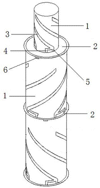
Figure 1 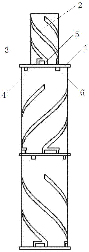
Figure 2 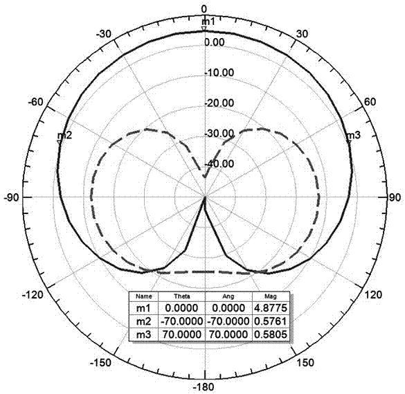
Figure 3
Abstract
Description
technical field
[0001] The invention relates to a satellite navigation buoy antenna for Beidou first generation L frequency band, S frequency band, Beidou second generation B1 frequency band and GPS L1 frequency band, in particular to a Beidou pole buoy antenna. Background technique
[0002] The rapid development of satellite navigation system plays an important role in national security, economic construction and daily life, and is widely used in military, transportation, surveying and mapping, safety monitoring and other fields. Satellite navigation terminal antenna is an indispensable and important part of satellite navigation terminal equipment, and its performance directly affects the performance of the whole machine. Therefore, satellite navigation terminal antenna has important research significance. At present, ceramic patch antennas, which are widely used in navigation terminal equipment, have the characteristics of small size and easy integration, but they are heav...
Examples
Embodiment Construction
[0016] Such as Figure 1~6 As shown, a Beidou rod-shaped buoy antenna includes a plurality of antenna units stacked together to form a rod-shaped structure, and the antenna unit includes a dielectric cylinder 1 and a feed network circuit board 2 at the bottom of the dielectric cylinder 1; A plurality of spiral arms 3 are arranged at intervals around the cylinder 1. The dielectric cylinder 1 is made of non-conductive material, and the spiral arm 3 is made of conductive material. The spiral arms 3 are inlaid or etched on the wall of the dielectric cylinder 1, which is beneficial to reduce the weight of the antenna. To meet the lightweight requirements of the buoy terminal; the lower end of each spiral arm 3 is provided with a short-circuit stub 4 and a feed point 5, the feed network circuit board 2 is provided with a grounding plate and a microstrip feeder, and the short-circuit stub at the lower end of the spiral arm 3 4 is welded together with the ground plate on the feed netw...