
Four-shaft rotorcraft balance remediation device
A rotorcraft and balancing technology, applied in the field of balance and remedial devices for four-axis rotorcraft, can solve problems such as falling and danger, and achieve the effect of simple structure, ingenious structure, and overcoming the problem of imbalance recovery
Patent Information
- Authority / Receiving Office
- CN · China
- Patent Type
- Applications(China)
- Current Assignee / Owner
- Publication Date
- 2018-04-13
Smart Images
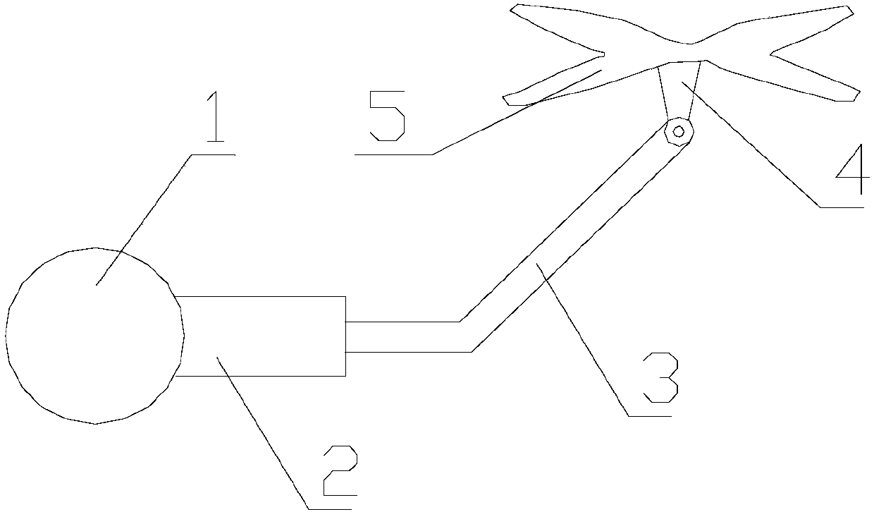
Figure 1 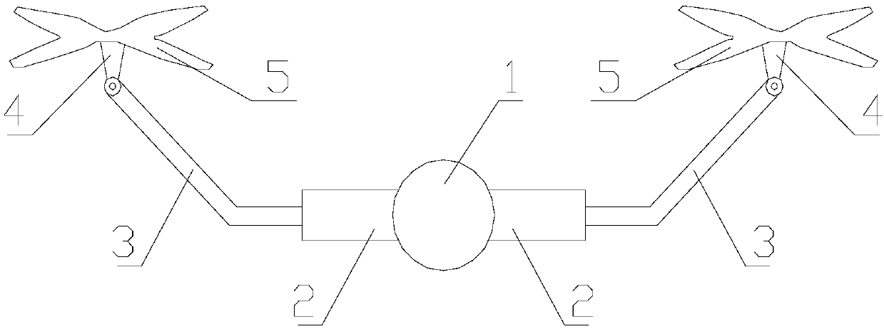
Figure 2 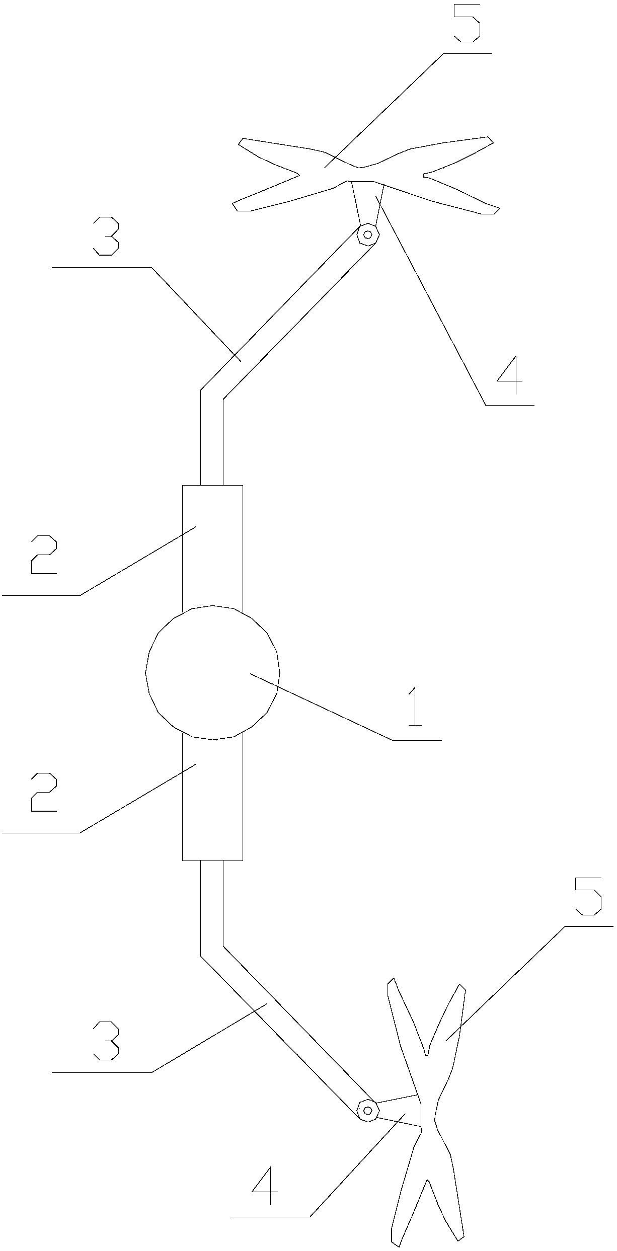
Figure 3
Abstract
Description
technical field
[0001] The invention relates to the technical field of four-axis rotorcraft, in particular to a balance remedy device for four-axis rotorcraft. Background technique
[0002] The four-axis rotorcraft is that the four rotors are symmetrically distributed in the front, rear, left, and right directions of the body. The four rotors are on the same height plane, and the structures and radii of the four rotors are the same. The four motors are symmetrically installed on the bracket end of the aircraft. , the space in the middle of the bracket places the flight control computer and external equipment. By adjusting the rotation speed of the four motors to change the rotation speed of the rotor, the lift force can be changed, thereby controlling the attitude and position of the aircraft. Quadrotor aircraft is a vertical elevator with six degrees of freedom, but it has only four input forces and six state outputs at the same time, so it is an underactuated system. [...
Examples
Embodiment Construction
[0019] The present invention will be described in detail below in conjunction with the accompanying drawings. The description in this part is only exemplary and explanatory, and should not have any limiting effect on the protection scope of the present invention.
[0020] Such as Figures 1 to 4 As shown, a four-axis rotorcraft balance remedial device includes a body 1, a wing column 2, a blade rod 3, a motor 4 and a blade 5, the wing column 2 is fixedly connected to the body 1, and the blade rod 3. One end is coaxially connected to the wing post 2, and the other end is connected to the motor 4 for rotation; the output shaft of the motor 4 is fixedly connected to the paddle 5.
[0021] The device is provided with a wing column 2 on the side of the body 1, and the wing column 2 is rotatably connected to the blade rod 3, and the other end of the blade rod 3 is provided with a motor 4 and a blade 5, and the motor 4 drives the blade 5 Rotate to form a lifting force, and the motor...