
Cylindrical coordinate type industrial robot
An industrial robot, cylindrical coordinate technology, applied in manipulators, manufacturing tools, program-controlled manipulators, etc., can solve problems such as material push and labor costs
Patent Information
- Authority / Receiving Office
- CN · China
- Patent Type
- Applications(China)
- Current Assignee / Owner
- Publication Date
- 2021-03-02
- Estimated Expiration
- Not applicable · inactive patent
Smart Images
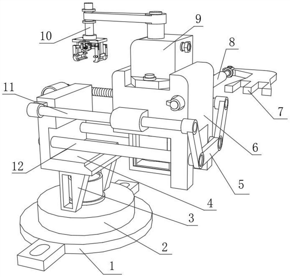
Figure 1 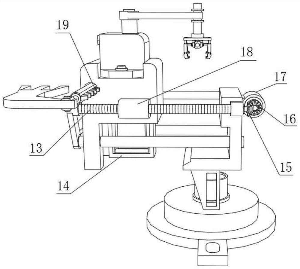
Figure 2 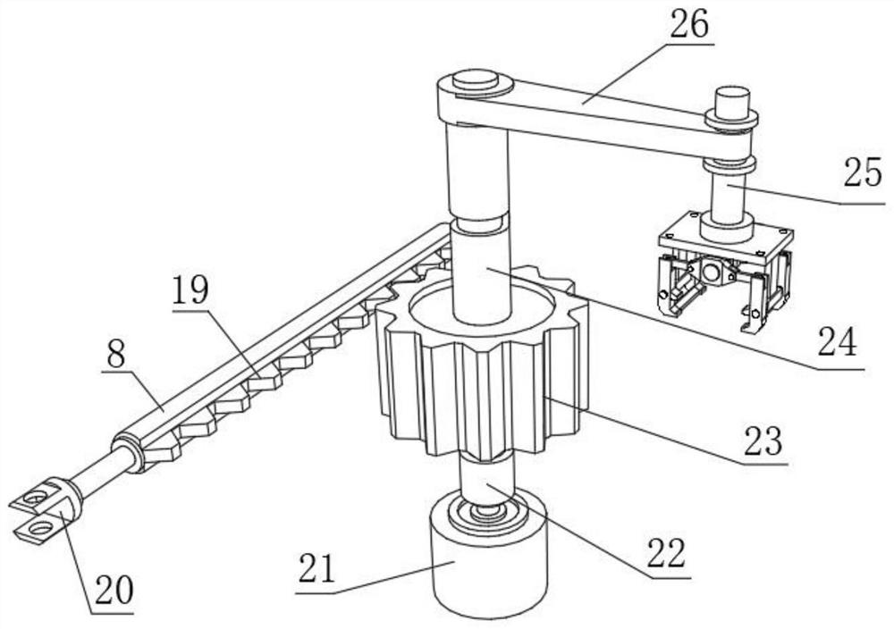
Figure 3
Abstract
Description
technical field
[0001] The invention relates to the technical field of cylindrical coordinate industrial robots, in particular to a cylindrical coordinate industrial robot. Background technique
[0002] An industrial robot is a multi-joint manipulator or a multi-degree-of-freedom machine device for the industrial field. It can perform work automatically. It is a machine that realizes various functions by its own power and control capabilities. It can accept human commands or follow instructions Running pre-programmed programs, modern industrial robots can also act according to the principles and programs formulated by artificial intelligence technology.
[0003] After searching, the Chinese patent application number is CN201710849542.X, which discloses a high-efficiency cylindrical coordinate industrial robot, including a robot body, a rotating groove is opened on the top of the robot body, and the bottom inner wall of the rotating groove A first installation groove is open...
Examples
Embodiment 1
[0034] A cylindrical coordinate industrial robot, such as Figure 1-6As shown, it includes a base 1, the top outer wall of the base 1 is fixed with a rotating disc 2 through bearings, and the top outer wall of the rotating disc 2 is fixed with two fixing frames 3 by bolts, and the top outer walls of the two fixing frames 3 are respectively fixed by bolts There is the same L-shaped connecting frame 4, two guide rods 12 are plugged into one side of the L-shaped connecting frame 4, and the outer walls on both sides of the L-shaped connecting frame 4 near the top of the two guiding rods 12 are respectively fixed with connecting blocks. The fixed rod 11 and the screw rod 13, the peripheral outer walls of the fixed rod 11 and the screw rod 13 are all sleeved with sliders 18, and the outer walls on the opposite sides of the two sliders 18 are respectively fixed with the same fixed seat 6 by bolts, and the top outer wall of the fixed seat 6 The installation box 9 is fixed by bolts, an...
Embodiment 2
[0039] A cylindrical coordinate industrial robot, such as Figure 4 As shown, in order to effectively promote the lifting of the manipulator after grabbing materials; this embodiment makes the following improvements on the basis of embodiment 1: a guide groove 30 is opened on one side of the outer wall of the guide post 24, and the structure of the guide groove 30 is L-shaped structure, and the outer wall of the installation box 9 near the guide groove 30 has a threaded hole, the threaded hole is fixed with a fixed threaded post 29, and the end of the fixed threaded post 29 near the guide groove 30 is welded with a sliding post 31, and the sliding post 31 is slidably connected In the guide groove 30; when the guide post 24 is in the process of rotation, the sliding post 31 can effectively limit the angle of the main gear 23, and in the process of rotation, the vertical lift of the guide post 24 is completed through the telescopic rod 22, by In this way, the effective lifting o...