
A vibrating and vibrating integrated sand and gravel screening device for concrete preparation
A screening device and concrete technology, which are applied in clay preparation devices, clay processing equipment, chemical instruments and methods, etc., can solve the problems of slow screening devices, high labor intensity and low efficiency of the screening device, and achieve simple structure and strong practicability. , the effect of reducing manufacturing costs
Patent Information
- Authority / Receiving Office
- CN · China
- Patent Type
- Patents(China)
- Current Assignee / Owner
- Publication Date
- 2020-08-14
Smart Images
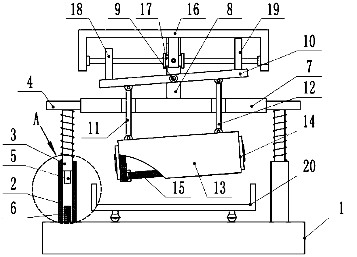
Figure 1 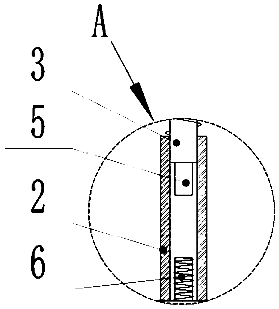
Figure 2 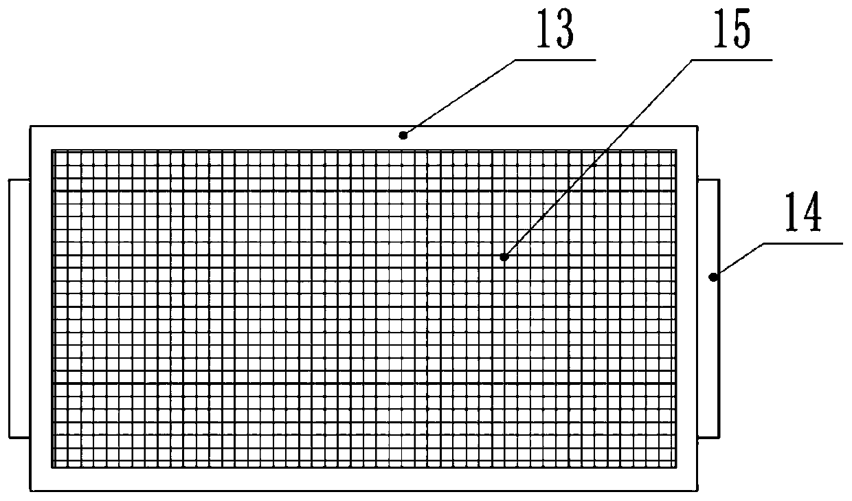
Figure 3
Abstract
Description
technical field
[0001] The invention relates to a grinding device, in particular to a vibration-vibration integrated sand and gravel screening device for concrete preparation. Background technique
[0002] Sand and gravel are commonly used in building decoration, and sand and gravel refer to a loose mixture of sand grains and crushed stones. In geology, mineral or rock particles with a particle size of 0.074~2mm are called sand, and those with a particle size larger than 2mm are called gravel or breccia (the difference between the two lies in the degree of rounding, see the entry conglomerate and sandstone for details. ). If most of the gravel in the sand is gravel, it is called sand gravel. Some people also refer to sandstone as sandstone in daily life.
[0003] Sand and gravel need to be screened before use. Sand and gravel with different particle sizes have inconsistent effects, so they need to be screened. In the prior art, the work throws sand and gravel onto the scr...
Examples
Embodiment Construction
[0019] The technical solution of this patent will be further described in detail below in conjunction with specific embodiments.
[0020] see Figure 1-3 , a vibrating integrated sand and gravel screening device for concrete preparation, including a base 1, an outer rod 2, an inner sliding rod 3, a horizontal plate 7, a swing rod 10, a screening box 13, a double-axis motor 17, a left cam 18 and Right cam 19, the left and right sides of the upper surface of the base 1 are fixedly welded with outer casing rod 2, the inside of the outer casing rod 2 is a hollow structure and the inside of the outer casing rod 2 is slidably equipped with an inner sliding rod 3, the inner sliding rod 3 is vertically upward and The upper end of the slide bar 3 is welded with a fixed block 4, a spring is connected between the lower side of the fixed block 4 and the outer rod 2, the inner slide bar 3 passes through the inner center of the spring, and the lower end of the inner slide bar 3 is also prov...