
Pulling force test method for ship lashing eye plate
A tensile test and cable eye plate technology, applied in the field of shipbuilding, can solve the problems of reduced test efficiency, poor test result accuracy, large error, etc., to achieve accurate test data, improve test speed and quality, and save sampling and multiple times. The effect of the test procedure
Patent Information
- Authority / Receiving Office
- CN · China
- Patent Type
- Applications(China)
- Current Assignee / Owner
- Publication Date
- 2018-11-20
Smart Images
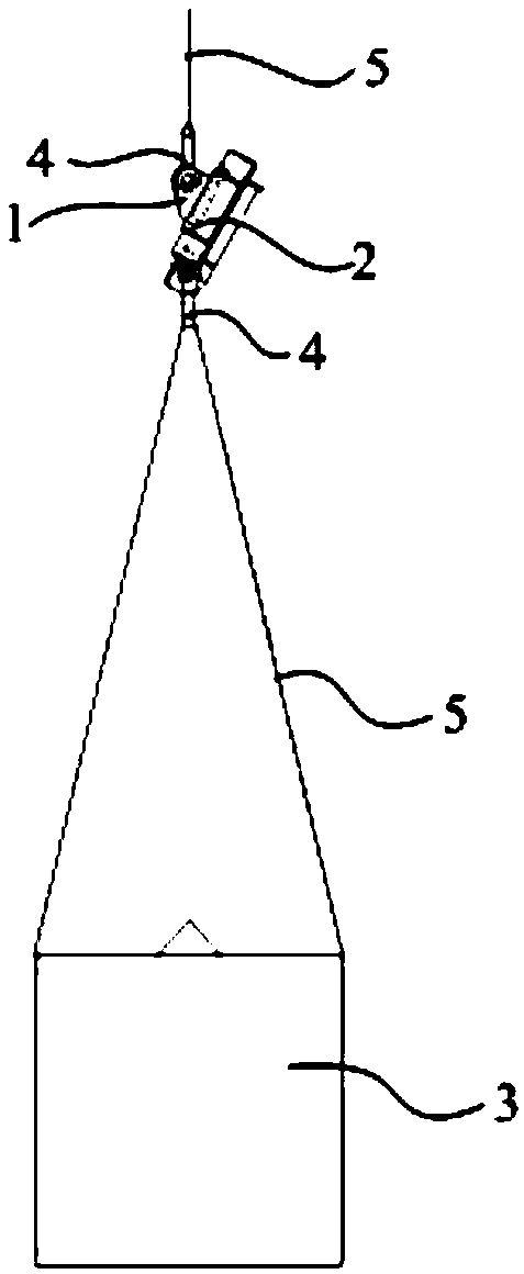
Figure 1 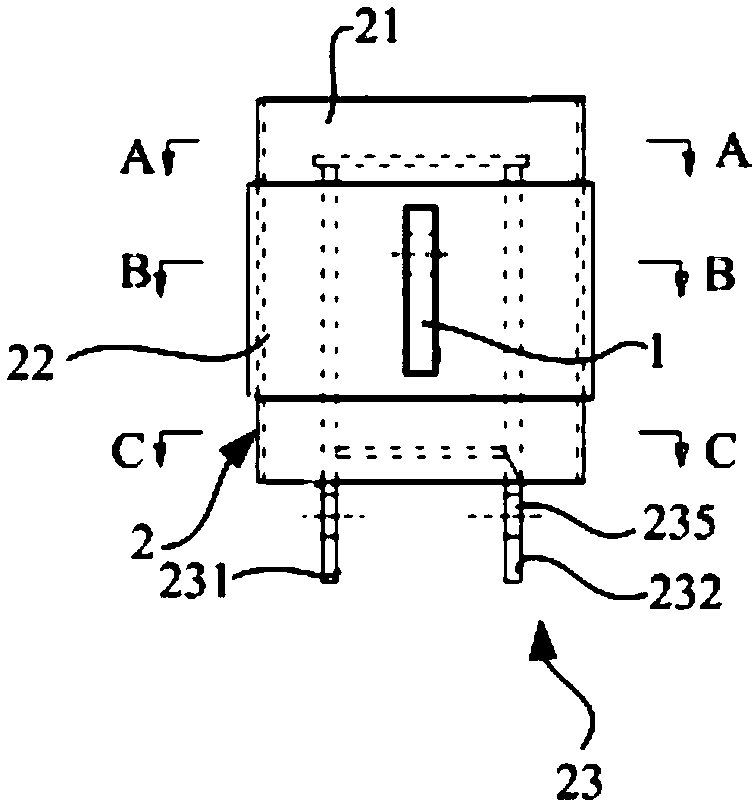
Figure 2 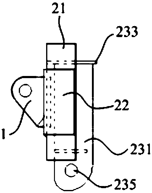
Figure 3
Abstract
Description
technical field
[0001] The invention relates to the technical field of shipbuilding, in particular to a tensile test method for a ship's mooring eye plate. Background technique
[0002] The rated load of the lanyard eye plate of the sailing ship (that is, the maximum working load that the lanyard eye plate can withstand when working) is 9.5T, and the installation node is a method of opening a hole on the mast and inserting welding. The eye plate of the lanyard is a strong stress member. According to the requirements of the classification society, such a strong stress member needs to be subjected to a tensile test before use. The tensile test of the existing lanyard eye plate is to carry out the sample tensile test in the laboratory after sampling. In order to improve the accuracy of the test, more than ten groups of samples are usually prepared for the test, and the tensile test is performed on each group of samples one by one. And form a record, and finally determine wheth...
Examples
Embodiment Construction
[0024] In order to make the technical problems solved by the present invention, the technical solutions adopted and the technical effects achieved clearer, the technical solutions of the embodiments of the present invention will be further described in detail below in conjunction with the accompanying drawings. Obviously, the described embodiments are only the technical solutions of the present invention. Some, but not all, embodiments. Based on the embodiments of the present invention, all other embodiments obtained by those skilled in the art without creative efforts fall within the protection scope of the present invention.
[0025] In the description of the present invention, unless otherwise clearly specified and limited, the terms "connected", "connected" and "fixed" should be understood in a broad sense, for example, it can be a fixed connection, a detachable connection, or an integrated ; It can be a mechanical connection or an electrical connection; it can be a direct...