
Hydraulic speed reduction device
A technology of hydraulic deceleration and speed, applied in the field of hydraulic machinery, can solve the problems of large idling loss of hydraulic reducer, failure to meet actual use needs, weakening deceleration and braking effect of hydraulic reducer, etc., to reduce idling loss, reduction in axial installation size, and reduction in installation cost
Patent Information
- Authority / Receiving Office
- CN · China
- Patent Type
- Applications(China)
- Current Assignee / Owner
- Publication Date
- 2019-08-02
Smart Images
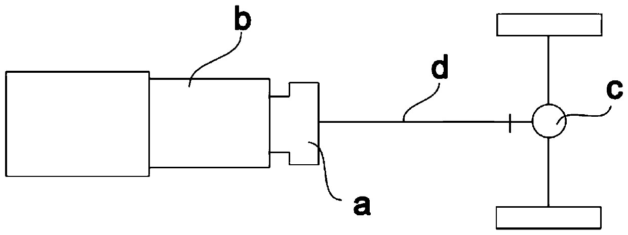
Figure 1 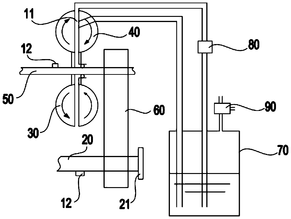
Figure 2 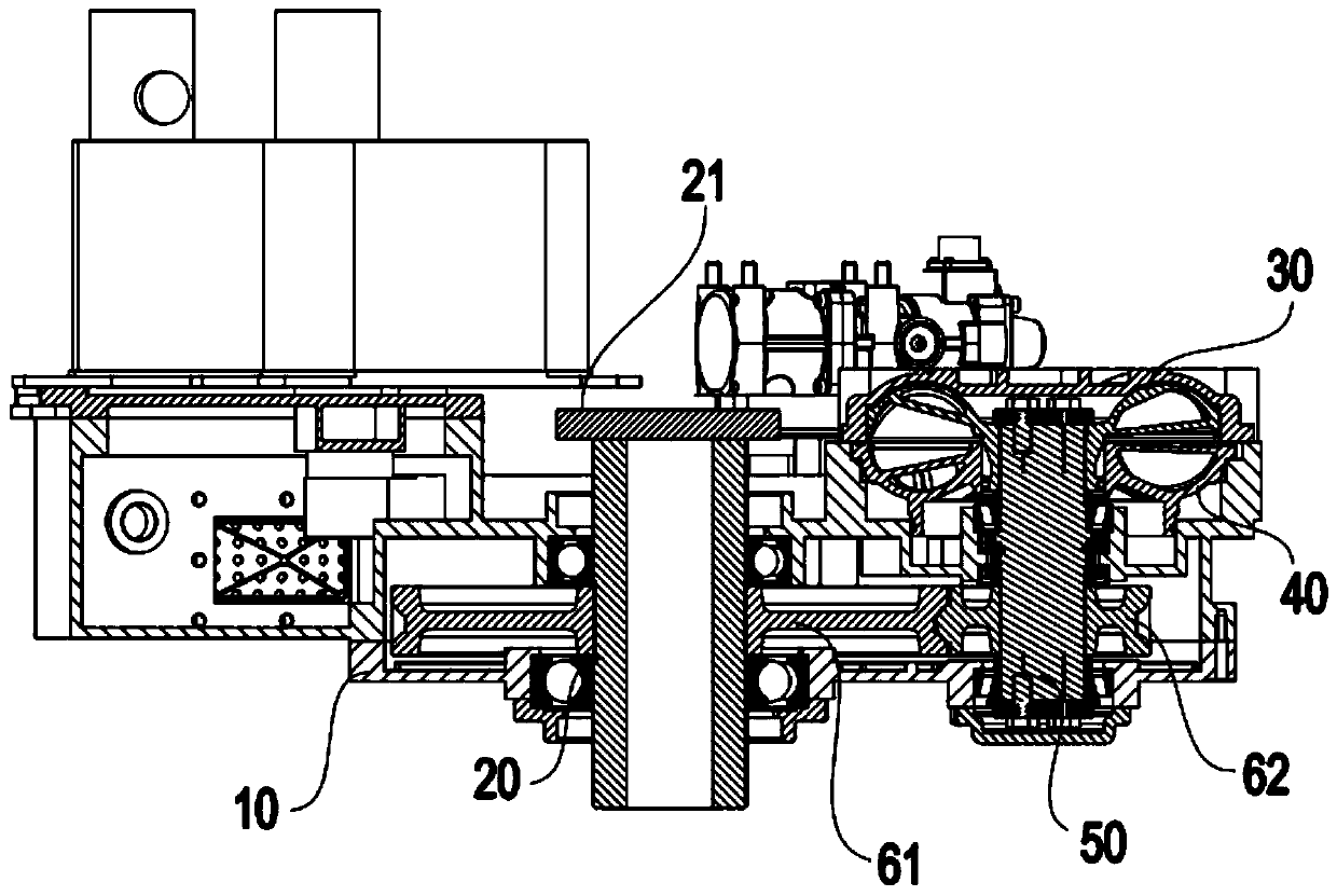
Figure 3
Abstract
Description
technical field
[0001] The invention relates to the technical field of hydraulic machinery, in particular to a hydraulic deceleration device installed between a vehicle gearbox and a vehicle drive axle. Background technique
[0002] For vehicles with high speed and heavy loads, and vehicles requiring short braking distance and quick response, traditional mechanical friction brakes alone cannot meet people's requirements for vehicle safety, and hydraulic retarders can safely and reliably assist vehicle braking. To make the vehicle meet the safety requirements, therefore, it is widely used in vehicles.
[0003] The hydraulic reducer is a device that converts mechanical energy into liquid heat energy and has low wear and tear. It is composed of a rotor impeller, a stator impeller, and a rapid liquid filling and discharging mechanism. A working chamber is formed between the rotor impeller and the stator impeller. When working, the rotor impeller is driven by the transmission sy...
Examples
Embodiment 1
[0033] combine image 3 and Figure 4 As shown, the speed regulating mechanism 60 includes a first speed change gear 61 and a second speed change gear 62, wherein the first rotating shaft 20 is pivotally connected to the first speed change gear 61, the second rotating shaft 50 is pivotally connected to the second speed change gear 62, and the first speed change gear 61 is meshed with the second transmission gear 62 . During specific implementation, the first rotating shaft 20 drives the first transmission gear 61 to rotate, and the first transmission gear 61 further drives the second transmission gear 62 meshed with it to rotate; the second transmission gear 62 drives the second rotation shaft 50 to rotate, and then drives the rotor The impeller 30 rotates so that the rotational speed of the rotor impeller 30 is changed under the action of the first speed change gear 61 and the second speed change gear 62 , thereby changing the braking torque of the hydraulic speed reduction ...
Embodiment 2
[0036] Such as Figure 5 As shown, the speed regulating mechanism 60 includes a first speed change gear 61, a second speed change gear 62, a third speed change gear 63, a fourth speed change gear 64 and a third rotating shaft 65, wherein the third rotating shaft 65 is pivotally connected to the third speed changing gear 63 and the fourth speed change gear 64, the first shaft 20 is pivotally connected to the first speed change gear 61, and the first speed change gear 61 is meshed with the third speed change gear 63, the second shaft 50 is pivotally connected to the second speed change gear 62, and the second The transmission gear 62 is engaged with the fourth transmission gear 64 .
[0037] During specific implementation, the first rotating shaft 20 drives the first transmission gear 61 to rotate, and the first transmission gear 61 further drives the third transmission gear 63 meshed with it to rotate; the second transmission gear 62 drives the third rotation shaft 65 to rotate, ...
Embodiment 3
[0040] Such as Figure 6 As shown, the speed regulating mechanism 60 includes a first speed change gear 61, a second speed change gear 62, a third speed change gear 63, a fourth speed change gear 64 and a clutch 66, wherein the first rotating shaft 20 is connected to the first speed change gear 61 and the second speed change gear 61. Three-speed gear 63, the second rotating shaft 50 is connected to the second speed-change gear 62 and the fourth speed-change gear 64, and the first speed-change gear 61 is meshed with the second speed-change gear 62, and the third speed-change gear 63 and the fourth speed-change gear 64 Further, the clutch 66 is installed on the second rotating shaft 50 and is located between the second transmission gear 62 and the fourth transmission gear 64, which can be connected with any of the second transmission gear 62 and the fourth transmission gear 64. One is combined, and it can also be separated from both the second speed change gear 62 and the fourth...