
Hydraulic variable-speed micro-miniature turbofan engine with multi-rotor structure
A hydraulic variable speed, turbofan technology, applied in the direction of machines/engines, gas turbine devices, mechanical equipment, etc., can solve the problems of high cost, high difficulty in processing and assembly, and high difficulty in modeling, so as to save costs and reduce manufacturing Difficulty, the effect of simplifying the rotor structure
Patent Information
- Authority / Receiving Office
- CN · China
- Patent Type
- Applications(China)
- Current Assignee / Owner
- Publication Date
- 2020-06-23
- Estimated Expiration
- Not applicable · inactive patent
Smart Images
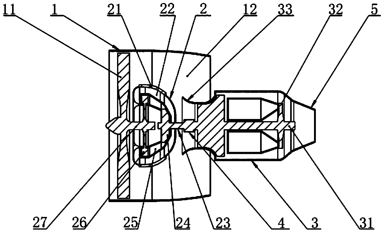
Figure 1 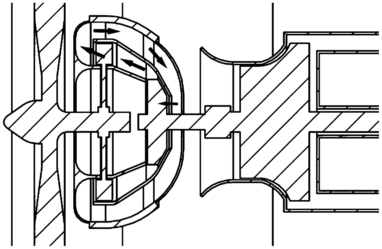
Figure 2
Abstract
Description
technical field
[0001] The present invention relates to a miniature turbofan engine, more specifically, to a miniature turbofan engine with hydraulically variable speed and multi-rotor structure. Background technique
[0002] With the continuous expansion of micro-aircraft in the fields of national defense, scientific research, and civil use, new and higher requirements have been put forward for the aircraft in terms of multi-mission, long range, high altitude, and high speed. Compared with the turbojet engine, the turbofan engine has better fuel economy, but the unique multi-rotor structure of the turbofan engine also brings great obstacles to the miniaturization of the engine. The diameter of the fan of the same turbofan engine is much larger than that of the rotor of the core engine, and the optimal speed of their work is very different, and they cannot run coaxially. Usually, the fan drive shaft of a turbofan engine with a dual-rotor structure needs to pass through the ...
Examples
Embodiment 1
[0029] like figure 1 As shown, a micro turbofan engine with hydraulically variable speed and multi-rotor structure includes a core engine 3 and a fan casing 1. The core engine 3 includes a core machine main shaft 31, and the front end of the core engine 3 is provided with a fan 11 and a speed reducer. The reducer includes a reducer input shaft 23, a reducer housing 2, a reducer output shaft 27, a power turbine 26 and a driving impeller 24. One end of the reducer output shaft 27 is connected to the fan 11, and the other end of the reducer output shaft 27 is connected to the power turbine 26. One end of the input shaft 23 of the reducer is connected with the driving impeller 24, the other end of the input shaft 23 of the reducer is connected with the coupling 4, the other end of the coupling 4 is connected with the main shaft 31 of the core machine, the fan case 1, the reducer The casing 2 and the core engine 3 together form an outer duct 12 . Wherein, the front end of the core...
Embodiment 2
[0032] like figure 1 As shown, the reducer housing 2 is provided with an independently rotating reducer output shaft 27 and an independently rotating reducer input shaft 23 , and there is no rigid connection between the reducer input shaft 23 and the reducer output shaft 27 . Compared with the reduction gearbox structure of large engines and the belt reducer structure of some micro engines, the rotor structure of the turbofan engine is greatly simplified, and the problem of wear and tear of the reduction gears is avoided, so that the hydraulic variable speed multi-rotor structure micro turbofan The engine reducer requires no lubrication and requires no maintenance for transmission parts, resulting in longer life.
Embodiment 3
[0034] like figure 2 As shown, the reducer housing 2 is respectively provided with a reducer outer flow channel 22 and a reducer inner flow channel 25 , and the reducer outer flow channel 22 communicates with the reducer inner flow channel 25 . Wherein, the reducer cooling fin 21 is arranged on the reducer casing 2 close to the reducer outer flow channel 22 . The reducer casing 2 is filled with liquid.
[0035] As a preferred embodiment, the outer diameter of the driving impeller 24 is smaller than the outer diameter of the power turbine 26, using hydraulic flow to transfer energy, and balance the speed difference between the fan 11 and the core machine, so as to achieve the purpose of working at the optimum speed respectively , thereby improving the cruising range and economy of the aircraft.
[0036] like figure 1 and 2As shown, those skilled in the art can implement the present invention as a micro-miniature turbofan engine with hydraulically variable speed and multi-r...