
High-precision real-time attitude measurement device and method based on antenna turret
A high-precision, turret technology, used in measurement devices, navigation through velocity/acceleration measurement, mapping and navigation, etc., can solve the problems of inappropriate antenna turret attitude measurement, large influence, large volume and weight, etc. Achieve the effect of improving orientation and attitude measurement accuracy, reducing rowing error, and reducing volume and weight
Patent Information
- Authority / Receiving Office
- CN · China
- Patent Type
- Applications(China)
- Current Assignee / Owner
- Publication Date
- 2021-01-22
Smart Images
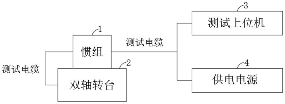
Figure 1 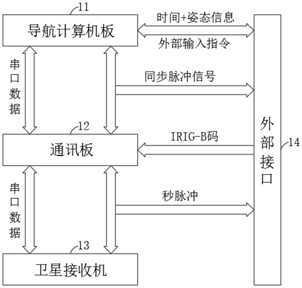
Figure 2 
Figure 3
Abstract
Description
technical field
[0001] The invention relates to the technical field of real-time directional attitude measurement, and more specifically, to a high-precision real-time attitude measurement device and method based on an antenna turret. Background technique
[0002] Strapdown inertial measurement unit (hereinafter referred to as "inertial unit") is widely used in azimuth and attitude measurement equipment on rockets, missiles, aircraft, etc. In order to improve the accuracy of orientation and attitude measurement, three high-precision laser gyroscopes and quartz The flexible accelerometer constitutes an inertial measurement unit (hereinafter referred to as "IMU"), which performs comprehensive calculations based on the angular velocity component of the earth's rotation sensed by the gyroscope and the gravity component sensed by the accelerometer to obtain the north azimuth and attitude angle.
[0003] In the traditional strapdown inertial group, the IMU is directly connected to...
Examples
Embodiment
[0028] The present invention utilizes the double-axis turntable 2 equivalent antenna turret to provide the transposition function. The position accuracy of the double-axis turntable 2 is 2″, and the inertial group 1 is installed on the double-axis turntable. For specific hardware connections, please refer to figure 1 and figure 2 , its specific hardware includes:
[0029] Navigation computer board 11;
[0030] Communication board 12, described communication board 12 is bidirectionally connected with navigation computer board 11 by serial port data, and is connected with navigation computer board 11 unidirectionally by synchronous pulse signal;
[0031] Satellite receiver 13, said satellite receiver 13 is bidirectionally connected with communication board 12 through serial port data, and is unidirectionally connected with communication board 12 through second pulse signal;
[0032] External interface 14, the navigation computer board 11 is bidirectionally connected to the ex...