

Elastic wave foil type cylindrical surface air film flexible supporting structure
A flexible support and corrugated foil technology, applied in the direction of engine sealing, engine components, mechanical equipment, etc., can solve the problems of wear of the rotor of the moving ring and the static ring, deformation of the sealing gas film, instability of the gas film, etc., to improve the support performance , Uniform structural stiffness, improve the effect of flexible support buffering and heat transfer performance
Patent Information
- Authority / Receiving Office
- CN · China
- Patent Type
- Applications(China)
- Current Assignee / Owner
- Publication Date
- 2021-04-13
Smart Images
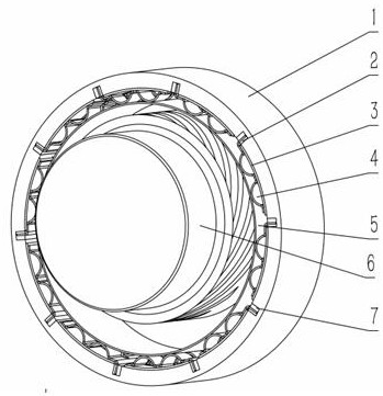
Figure 1 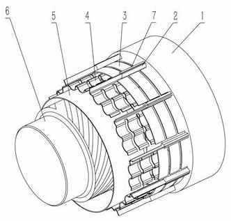
Figure 2 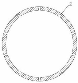
Figure 3
Abstract
Description
technical field
[0001] The invention relates to an elastic wave foil type cylinder air film flexible support structure, which is especially suitable for an axial sealing device of a rotating shaft of a high-speed rotating machine, and belongs to the technical field of non-contact mechanical sealing. Background technique
[0002] Sealing technology is one of the key technologies of aero-engines. Sealing technology plays a key role in improving mechanical work efficiency and ensuring reliability. The original traditional sealing methods all use contact seals, which are only suitable for low-speed rotating machines. For high-speed rotating machines, the contact seal structure will generate a lot of friction, which seriously affects the mechanical structure. Therefore, in high-speed rotating machines, non-contact seals are used. The sealing device is particularly important; the general aerospace field is the field of high-speed operation machinery, and the use of non-contact sea...
Examples
Embodiment 1
[0023] Embodiment 1: as Figure 1-8 As shown, an elastic wave foil type cylindrical air film flexible support structure includes an outer support sleeve 1, a flat plate 2, a corrugated foil 4, a static ring 5, a moving ring rotor 6, and a pressure block 7; There is a slot 601, the static ring 5 is eccentrically installed on the moving ring rotor 6, the outer support sleeve 1 and the static ring 5 are coaxially installed on the external structure, and the inner wall of the outer support sleeve 1 is provided with 8 card slots 101 , the corrugated foil 4 is provided with an arc plate 3, the arc plate 3 is located on the inner peripheral wall of the outer support sleeve 1, the flat plate 2 is installed on the inner side of the card slot 101, and the corrugated foil 4 is installed close to the flat plate 2 In the card slot 101, the pressing block 7 is pressed into the other side of the card slot 101, the corrugated foil 4 is in linear contact with the outer wall of the static ring ...
Embodiment 2
[0026] Embodiment 2: as Figure 1-8 As shown, an elastic wave foil type cylindrical air film flexible support structure includes an outer support sleeve 1, a flat plate 2, a corrugated foil 4, a static ring 5, a moving ring rotor 6, and a pressure block 7; There is a slot 601, the static ring 5 is eccentrically installed on the moving ring rotor 6, the outer support sleeve 1 and the static ring 5 are coaxially installed on the external structure, and the inner wall of the outer support sleeve 1 is provided with 12 card slots 101 , the corrugated foil 4 is provided with an arc plate 3, the arc plate 3 is located on the inner peripheral wall of the outer support sleeve 1, the flat plate 2 is installed on the inner side of the card slot 101, and the corrugated foil 4 is installed close to the flat plate 2 In the card slot 101, the pressing block 7 is pressed into the other side of the card slot 101, the corrugated foil 4 is in linear contact with the outer wall of the static ring...
Embodiment 3
[0029] Embodiment 3: as Figure 1-8 As shown, an elastic wave foil type cylindrical air film flexible support structure includes an outer support sleeve 1, a flat plate 2, a corrugated foil 4, a static ring 5, a moving ring rotor 6, and a pressure block 7; There are slots 601, the static ring 5 is eccentrically installed on the moving ring rotor 6, the outer support sleeve 1 and the static ring 5 are coaxially installed on the external structure, and the inner wall of the outer support sleeve 1 is provided with 16 card slots 101 , the corrugated foil 4 is provided with an arc plate 3, the arc plate 3 is located on the inner peripheral wall of the outer support sleeve 1, the flat plate 2 is installed on the inner side of the card slot 101, and the corrugated foil 4 is installed close to the flat plate 2 In the card slot 101, the pressing block 7 is pressed into the other side of the card slot 101, the corrugated foil 4 is in linear contact with the outer wall of the static ring...