
Mounting technology of energy-saving heat exchange assembly
A technology of heat exchange components and installation process, which is applied to the types of heat exchangers, heat exchanger shells, indirect heat exchangers, etc., and can solve the problems of slow installation efficiency, lack of good assembly mechanism, unfavorable external personnel installation and processing work, etc. problems, to achieve high heat exchange efficiency
Patent Information
- Authority / Receiving Office
- CN · China
- Patent Type
- Applications(China)
- Current Assignee / Owner
- Publication Date
- 2021-06-01
- Estimated Expiration
- Not applicable · inactive patent
Smart Images
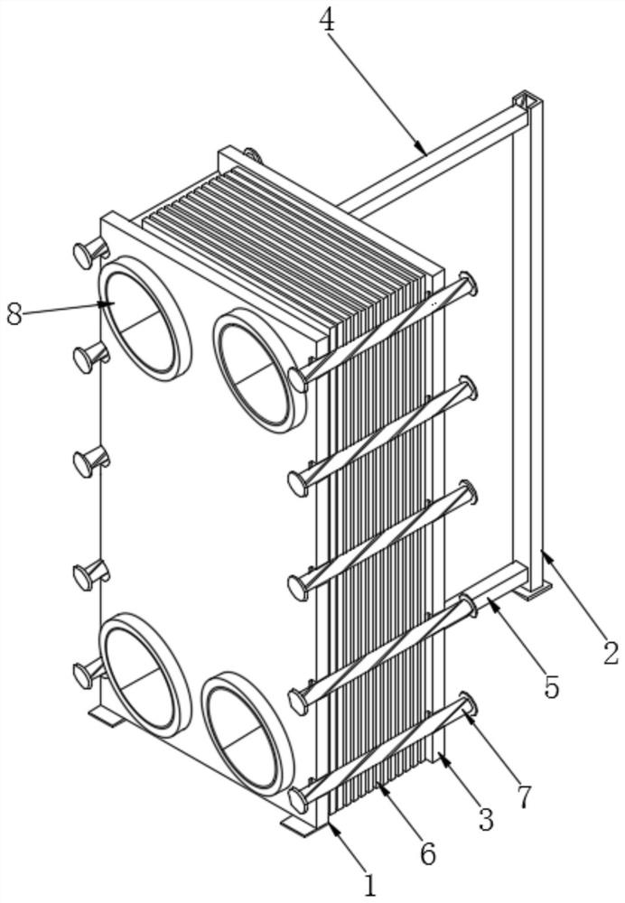
Figure 1 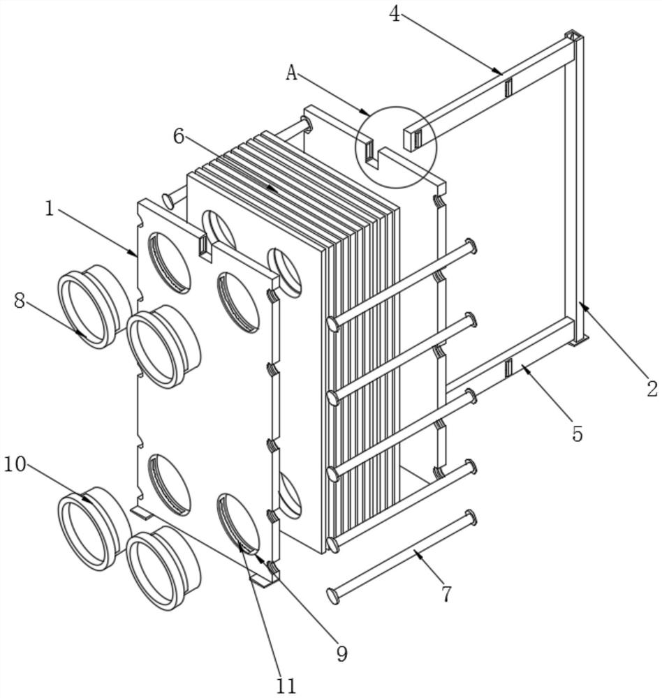
Figure 2 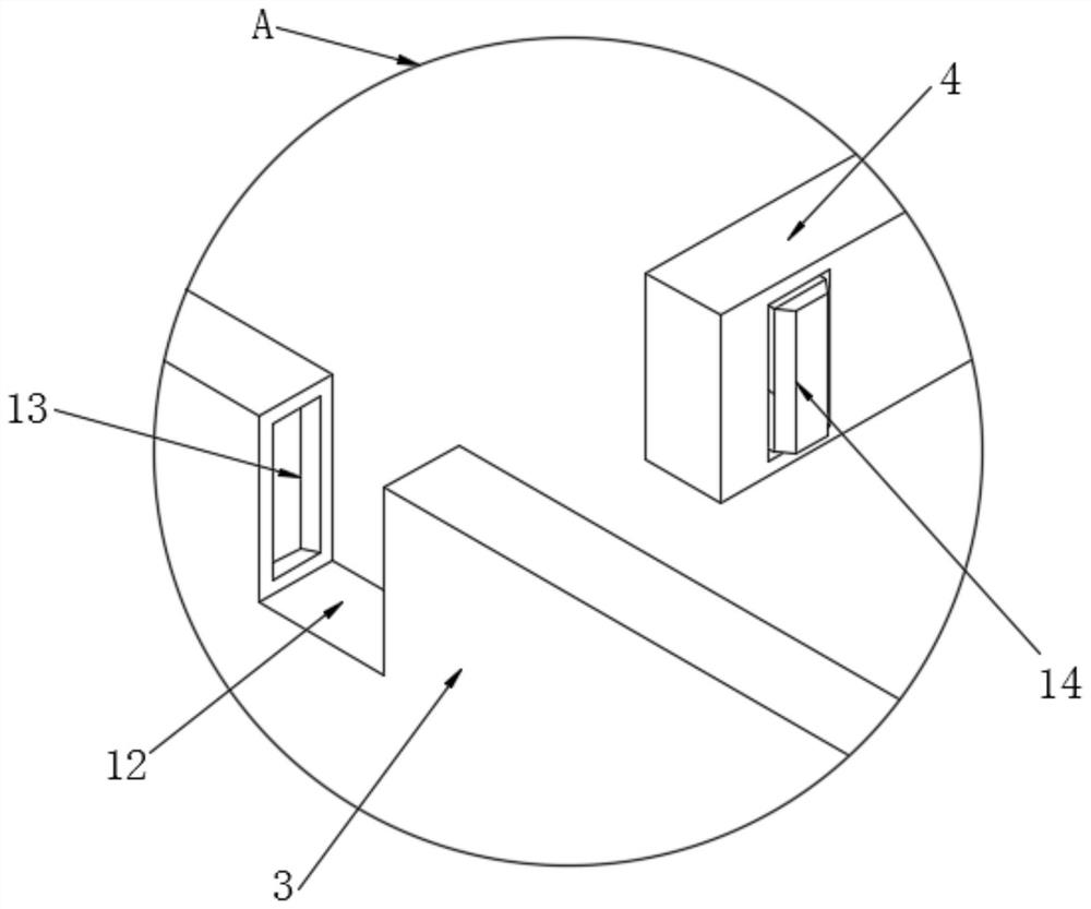
Figure 3
Abstract
Description
technical field
[0001] The invention relates to the technical field of electromechanical equipment installation, in particular to an installation process of an energy-saving heat exchange component. Background technique
[0002] The heat exchange unit is composed of heat exchanger, temperature control valve group, drain valve group, circulation pump, electric control cabinet, base, pipeline, valve, instrument, etc., and can be equipped with expansion tank, water treatment equipment, water pump frequency conversion control , temperature control valve, remote communication control, etc., thus forming a complete heat exchange station. The plate heat exchanger is a thin rectangular channel formed between various plates, and the heat is exchanged through the plates. The plate heat exchanger is a liquid- Ideal equipment for heat exchange between liquid and liquid-vapor.
[0003] When installing and processing energy-saving heat exchange components, because there is no good assemb...
Examples
Embodiment Construction
[0031] The following will clearly and completely describe the technical solutions in the embodiments of the present invention with reference to the accompanying drawings in the embodiments of the present invention. Obviously, the described embodiments are only some, not all, embodiments of the present invention. Based on the embodiments of the present invention, all other embodiments obtained by persons of ordinary skill in the art without making creative efforts belong to the protection scope of the present invention.
[0032] The present invention provides a technical solution: energy-saving heat exchange component installation process, including the following steps:
[0033] S1. Pendant handling work: hoist the corresponding installation board and various installation devices. During the hoisting process, the sling should not be hung on the connecting pipe, positioning beam or plate, and hoist the various connecting devices to the designated area. ;
[0034] S2. Reserved s...