
Tooth measuring equipment for different tooth widths
A technology of measuring equipment and teeth, applied in the direction of measuring device, mechanical measuring device, using mechanical device, etc., can solve the problems of poor accuracy, insufficient roundness of cutting line, affecting cutting work, etc., to improve accuracy and speed up drying effect of speed
Patent Information
- Authority / Receiving Office
- CN · China
- Patent Type
- Applications(China)
- Current Assignee / Owner
- Publication Date
- 2022-04-26
- Estimated Expiration
- Not applicable · inactive patent
Smart Images
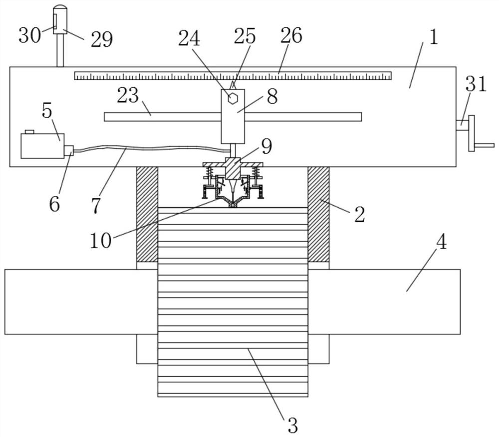
Figure 1 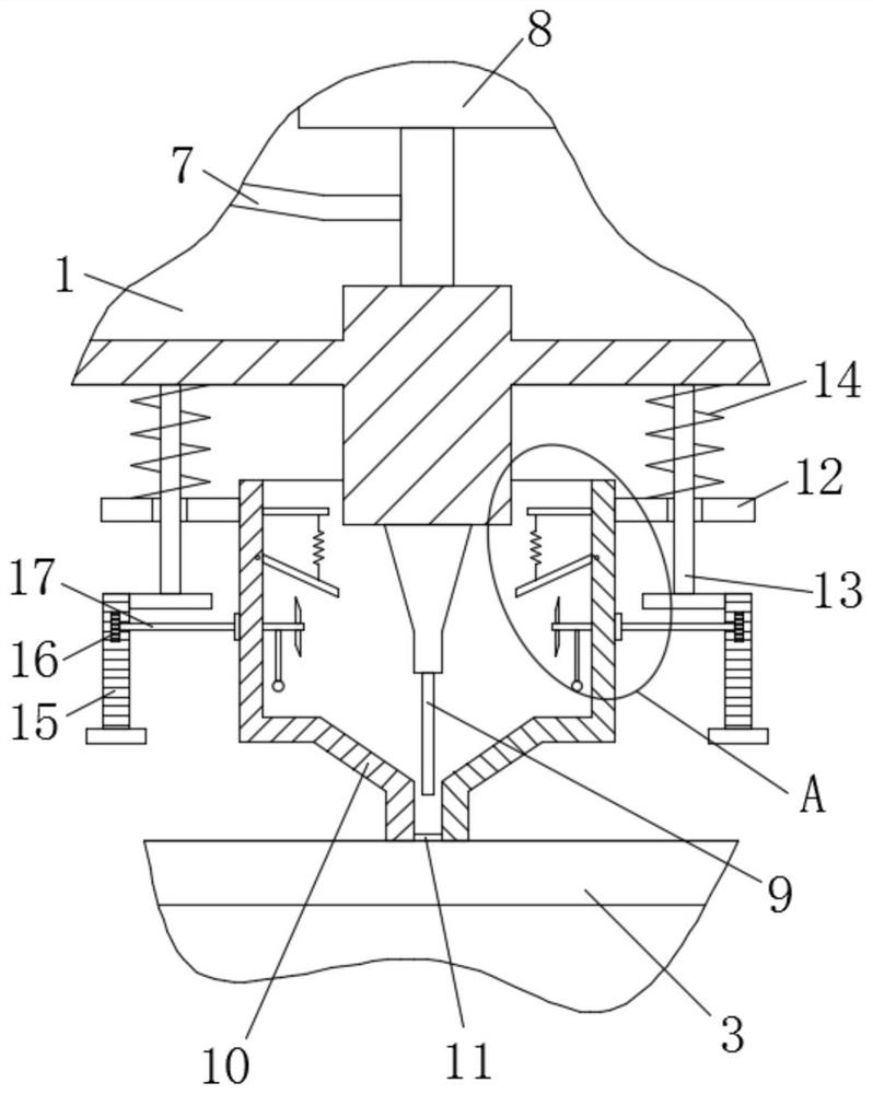
Figure 2 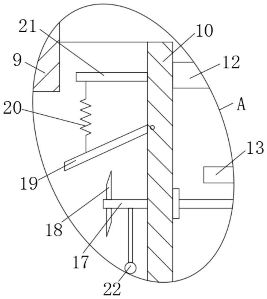
Figure 3
Abstract
Description
technical field
[0001] The invention relates to the technical field of tooth width measurement, in particular to a tooth measuring device for different tooth widths. Background technique
[0002] A gear is a mechanical element with gears on the rim that continuously mesh to transmit motion and power. The application of gears in transmission has appeared very early. At the end of the 19th century, the principle of generative gear cutting method and special machine tools and cutting tools using this principle appeared one after another. With the development of production, the stability of gear operation was paid more attention.
[0003] After searching, the patent with application number CN108332636B discloses "a measuring tool for measuring the tooth width of a planetary shaft", which includes a main body, a locking fixing groove runs through the bottom of the main body and the left and right sides, and the top of the main body An inner groove is arranged at the central pos...
Examples
Embodiment 1
[0043] refer to Figure 1-10 , a tooth measuring device for different tooth widths, comprising a measuring device body 1, a positioning plate 2 is slidably connected to the left and right sides of the lower end of the measuring device body 1, and two screw rods are threaded on the positioning plate 2 31. The threads on the left and right sides of screw mandrel 2 31 are oppositely arranged, and the screw mandrel 2 31 runs through the right end of the measuring device body 1, and the screw mandrel 2 31 is connected to the measuring device body 1 by rotation, and the lower side of the measuring device body 1 A gear body 3 is provided, and the gear body 3 is located between the positioning plates 2 on both sides. The ends of the positioning plates 2 that are close to each other are fitted with the gear body 3, and the gear shaft 4 is fixedly installed on the gear body 3. The measurement A paint box 5 is fixedly installed on the left side of the front end of the equipment body 1, a...
Embodiment 2
[0046] refer to Figure 1-10 , in this embodiment, it is basically the same as Embodiment 1, and more optimally, the ends of the connecting rods 13 that are far away from each other are fixedly installed with a rack 15, and the front end of the rack 15 is engaged with a transmission gear 16, and the transmission gears 16 are close to each other. Rotating shafts 17 are fixedly installed at one end of the rotating shafts 17, and the rotating shafts 17 run through the left and right ends of the protective shell 10 respectively. The upper side of the fan blade 18 is provided with a movable rotating plate 19, and one end of the movable rotating plate 19 away from each other is hinged with the inner wall of the protective shell 10. The upper end of the movable rotating plate 19 is fixedly equipped with a spring two 20, and the upper end of the spring two 20 is fixedly installed with a A horizontal plate 21, one end of the horizontal plate 21 away from each other is fixedly connected...
Embodiment 3
[0049] refer to Figure 1-10 , in this embodiment, it is basically the same as Embodiment 1, and more optimally, the front end of the measuring device body 1 is provided with a chute 23 corresponding to the slider 8, and the slider 8 is slidably connected to the measuring device body 1, and the chute 23 The shape of the fuel injection nozzle 9 is set in a "T" shape. A slider 8 is fixedly installed on the upper end of the fuel injection nozzle 9. A locking screw 24 is threaded on the upper end of the slider 8. The rear end of the locking screw 24 is attached to the surface of the measuring device body 1. Together, the upper end of the slider 8 is fixedly equipped with a pointer 25, the upper side of the pointer 25 is provided with a scale 26, the rear end of the scale 26 is fixedly connected to the measuring device body 1, and the rear side of the gear shaft 4 is provided with a limit circular plate 27, the limit The circular plate 27 is attached to the surface of the gear shaf...