
A CMOS voltage comparator
A technology of voltage comparator and MOS tube, which is applied in the direction of electrical components, logic circuits, generating electric pulses, etc., can solve the problems affecting the accuracy of comparators, slow conversion speed, and failure to work normally, and achieve large input dynamic range and comparison speed Fast, comparatively high-precision results
Patent Information
- Authority / Receiving Office
- CN · China
- Patent Type
- Patents(China)
- Current Assignee / Owner
- Publication Date
- 2006-10-11
- Estimated Expiration
- Not applicable · inactive patent
Smart Images
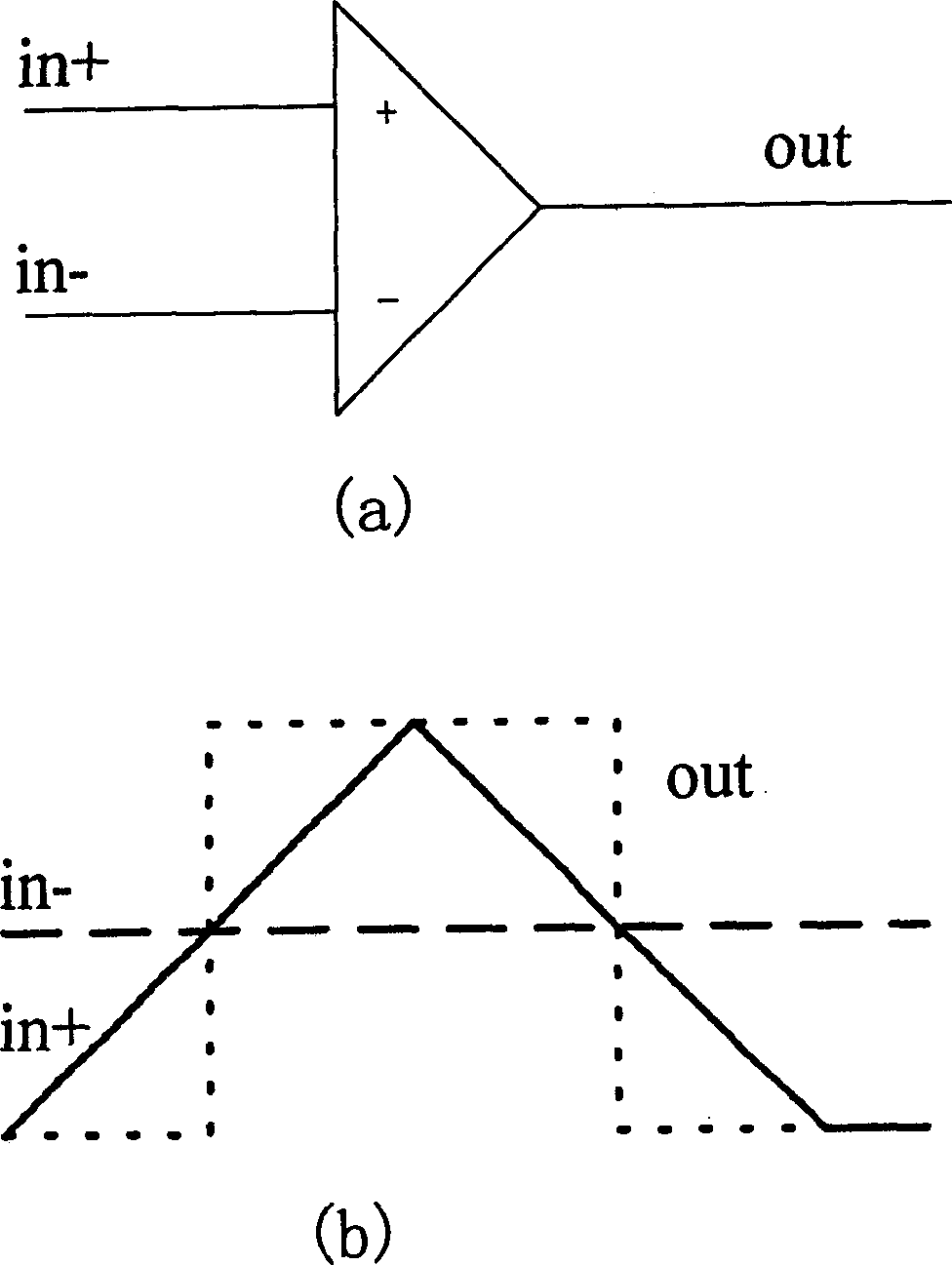
Figure 1 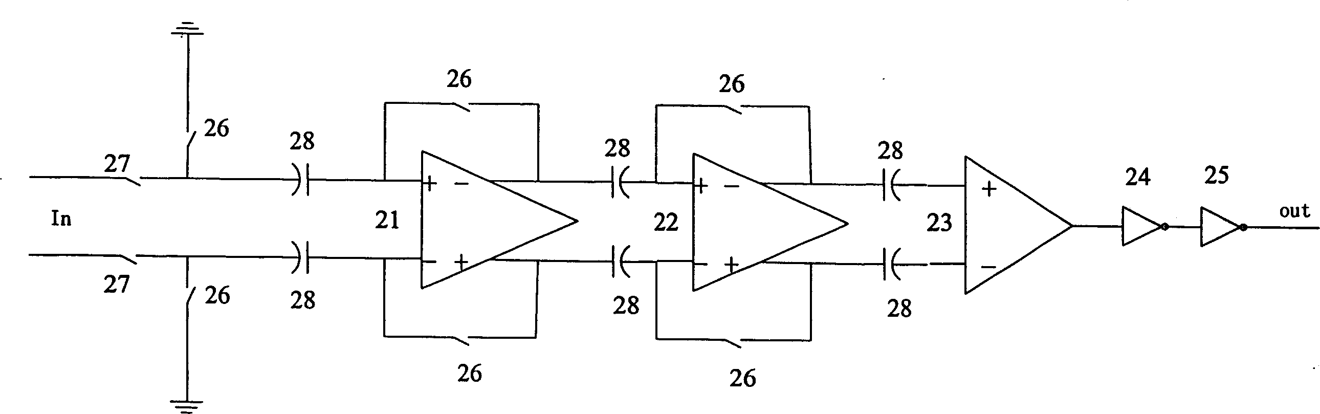
Figure 2 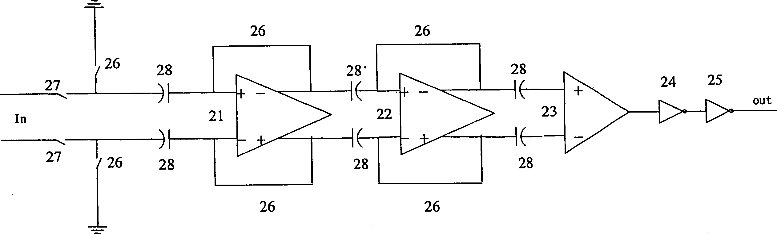
Figure 3
Abstract
Description
technical field
[0001] The invention relates to a voltage comparator, in particular to a CMOS voltage comparator composed of multi-level circuits. Background technique
[0002] In the traditional comparator in the integrated circuit, the operational amplifier is usually used as the comparator, and the comparison function is realized by utilizing the characteristic of the large open-loop gain of the operational amplifier. If the input voltage of the positive terminal is higher than that of the negative terminal, the output will be a high level; if the input voltage of the positive terminal is lower than that of the negative terminal, a low level will be output. In this way, the comparison of the input voltage at the positive and negative input terminals is realized. The functional block diagram and working principle diagram of the circuit are shown in figure 1 as shown, figure 1 (a) is a functional block diagram, figure 1 (b) is the working principle diagram, in which the...
Examples
Embodiment Construction
[0025] The technical solution of the present invention will be further described below in conjunction with the embodiments and the accompanying drawings.
[0026] figure 2 is a structural block diagram of an embodiment of the CMOS voltage comparator of the present invention, in which two stages of amplifiers are cascaded, such as figure 2 mentioned, including:
[0027] The first amplifier 21, its first output end is connected with the first input end through a switch 26, its second output end is connected with the second input end through a switch 26, two switches are opened or closed at the same time, can be regarded as unified Operational, so marked with the same symbol in the figure;
[0028] The second amplifier 22, the input end is connected with the output end of the first amplifier 21, its first output end is connected with the first input end through a switch 26, and its second output end is connected with the second input end through a switch 26, which The two sw...