
Printing plate removing/supplying device
a technology for supplying devices and printing plates, which is applied in the directions of pile separation, transportation and packaging, article separation, etc., can solve the problems of increasing the cost of the device, large space needed for the placement of the device, and heavy printing plates, and achieves the effect of less spa
Patent Information
- Authority / Receiving Office
- US · United States
- Patent Type
- Applications(United States)
- Current Assignee / Owner
- Publication Date
- 2004-09-30
- Estimated Expiration
- Not applicable · inactive patent
Smart Images
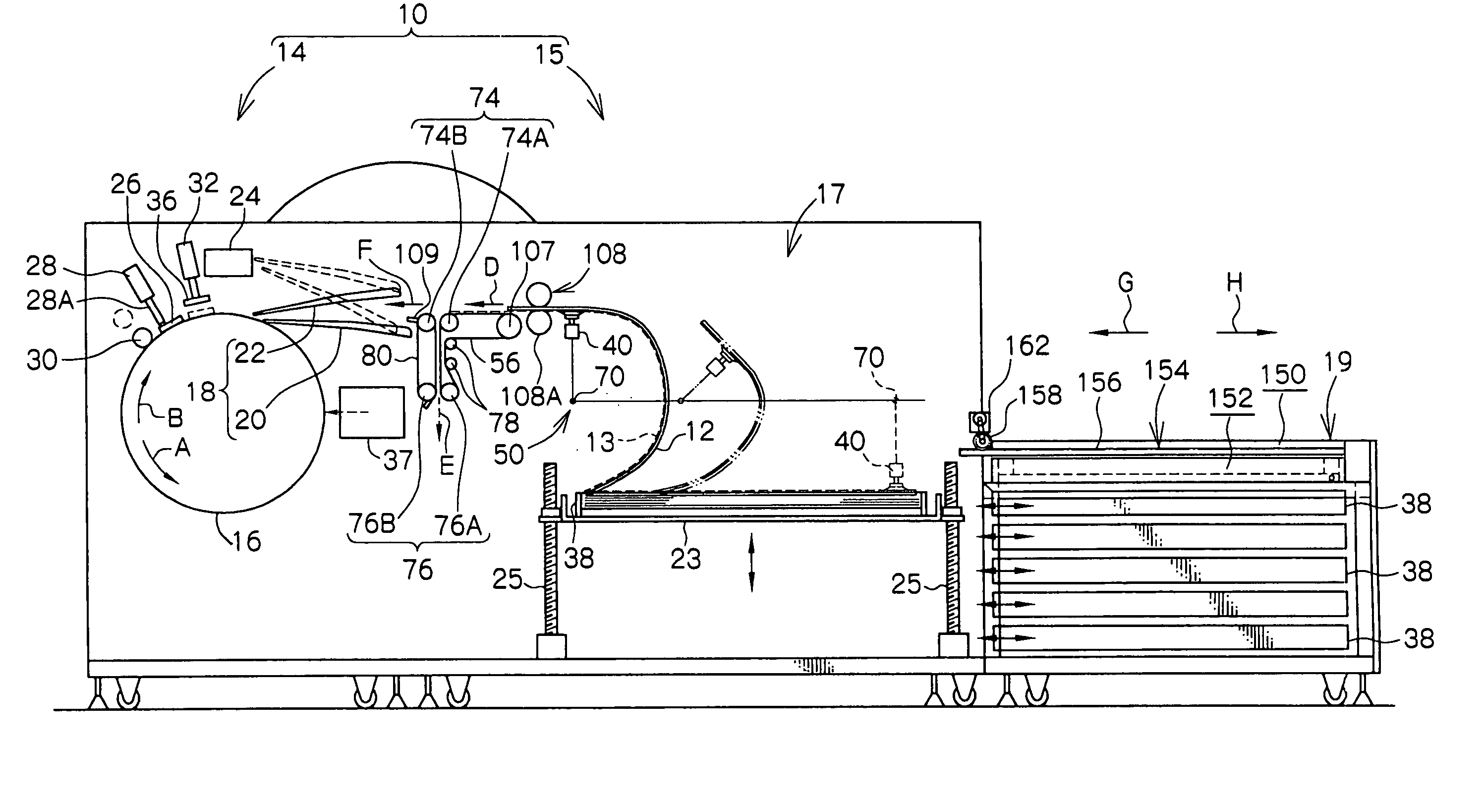
Figure 1 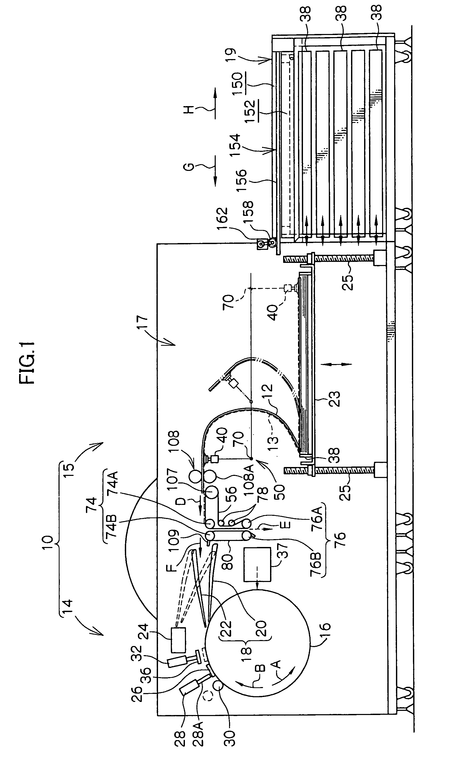
Figure 2 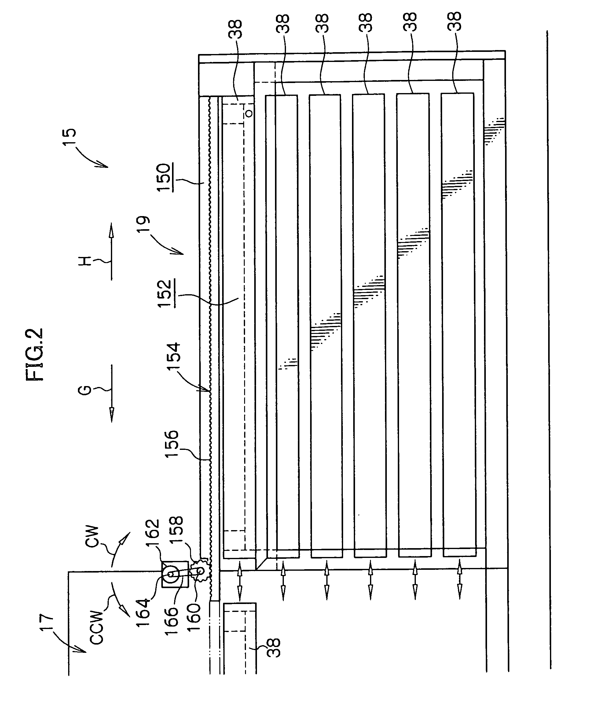
Figure 3
Abstract
Description
Cross-Reference to Related Application
[0001] This application claims priority under 35 USC 119 from Japanese Patent Application No. 2003-83392, the disclosure of which is incorporated by reference herein.BACKGROUND OF THE INVENTION
[0002] 1. Field of the Invention
[0003] The present invention relates to a printing plate removing / supplying device which removes a predetermined printing plate from plural cassettes in which printing plates are respectively accommodated, and conveys and supplies the predetermined printing plate to a section-to-be-supplied-to, which is a subsequent process.
[0004] 2. Description of the Related Art
[0005] A technique in which, by using a printing plate (e.g., a PS plate, a thermal plate, a photopolymer plate) in which a recording layer (photosensitive layer) is provided on a support, an image is recorded directly by a laser beam or the like onto the photosensitive layer of the printing plate, has come to be developed as a printing plate exposing device. With t...
Examples
first embodiment
[0028] The schematic overall structure of an automatic printing plate exposing device 10, to which a sheet sucking / feeding device 50 relating to the present invention is applied, is shown in FIG. 1.
[0029] The automatic printing plate exposing device 10 is divided into two main sections which are an exposure section 14, which illuminates a light beam onto an image forming layer of a printing plate 12 so as to expose an image, and a sheet feeding / conveying section 15 which removes the printing plate 12 and conveys the printing plate 12 to the exposure section 14. The printing plate 12, which has been subjected to exposure processing by the automatic printing plate exposure device 10, is fed out to a developing device (not illustrated) which is disposed adjacent to the automatic printing plate exposure device 10.
[0030] Structure of Exposure Section
[0031] The exposure section 14 is structured such that a rotating drum 16, around whose peripheral surface the printing plate 12 is trained ...
second embodiment
[0085] (Second Embodiment)
[0086] Next, a second embodiment will be described. Structures and operations which are basically the same as those of the above-described first embodiment are denoted by. the same reference numerals as in the first embodiment, and description thereof is omitted.
[0087] The structure of a cassette stocker portion 170 serving as an accommodating portion relating to the second embodiment of the present invention is shown in side view in FIG. 3.
[0088] The cassette stocker portion 170 basically has the same structure as that of the cassette stocker portion 19 relating to the above-described first embodiment. However, at the cassette stocker portion 170, the cover member is a shutter 172 which is flexible.
[0089] The end portions of the shutter 172 in the transverse direction thereof (the direction orthogonal to the surface of the drawing of FIG. 3) are fixed to two chains 174 which are provided at the end portions of the cassette stocker portion 170 in the transv...
third embodiment
[0104] (Third Embodiment)
[0105] Next, a third embodiment will be described. Structures and operations which are basically the same as those of the above-described first embodiment are denoted by the same reference numerals as in the first embodiment, and description thereof is omitted.
[0106] The structure of a cassette stocker portion 200 serving as an accommodating portion relating to the third embodiment of the present invention is shown in side view in FIG. 4.
[0107] The cassette stocker portion 200 basically has the same structure as that of the cassette stocker portion 19 relating to the above-described first embodiment. However, in the present third embodiment, the cover member is a folding cover 202 which can be folded over.
[0108] The folding cover 202 has a plate member 204 and a plate member 206, each of which is shaped as a rectangular, flat plate, and which are formed in the same configurations and to the same dimensions. The plate member 204 and the plate member 206 are b...