
Signal-quality evaluation device, signal adjustment method, optical-signal evaluation system, and optical transmission system
Patent Information
- Authority / Receiving Office
- US · United States
- Current Assignee / Owner
- Publication Date
- 2006-07-20
- Estimated Expiration
- Not applicable · inactive patent
Smart Images
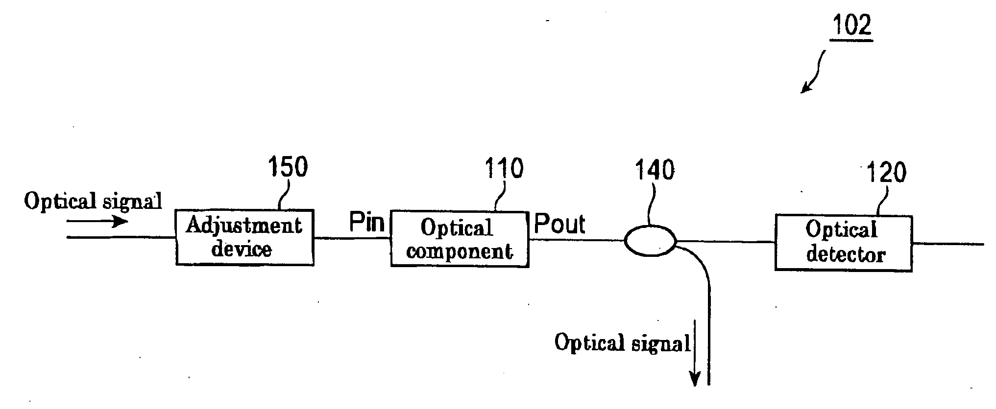
Figure 1 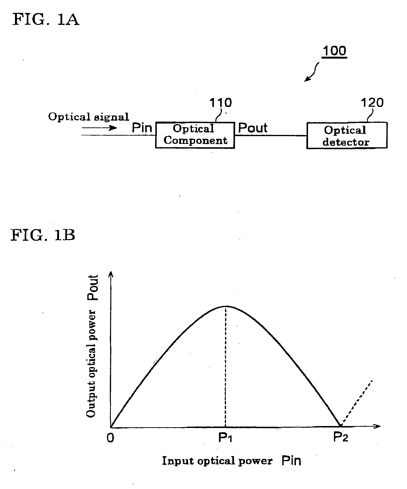
Figure 2 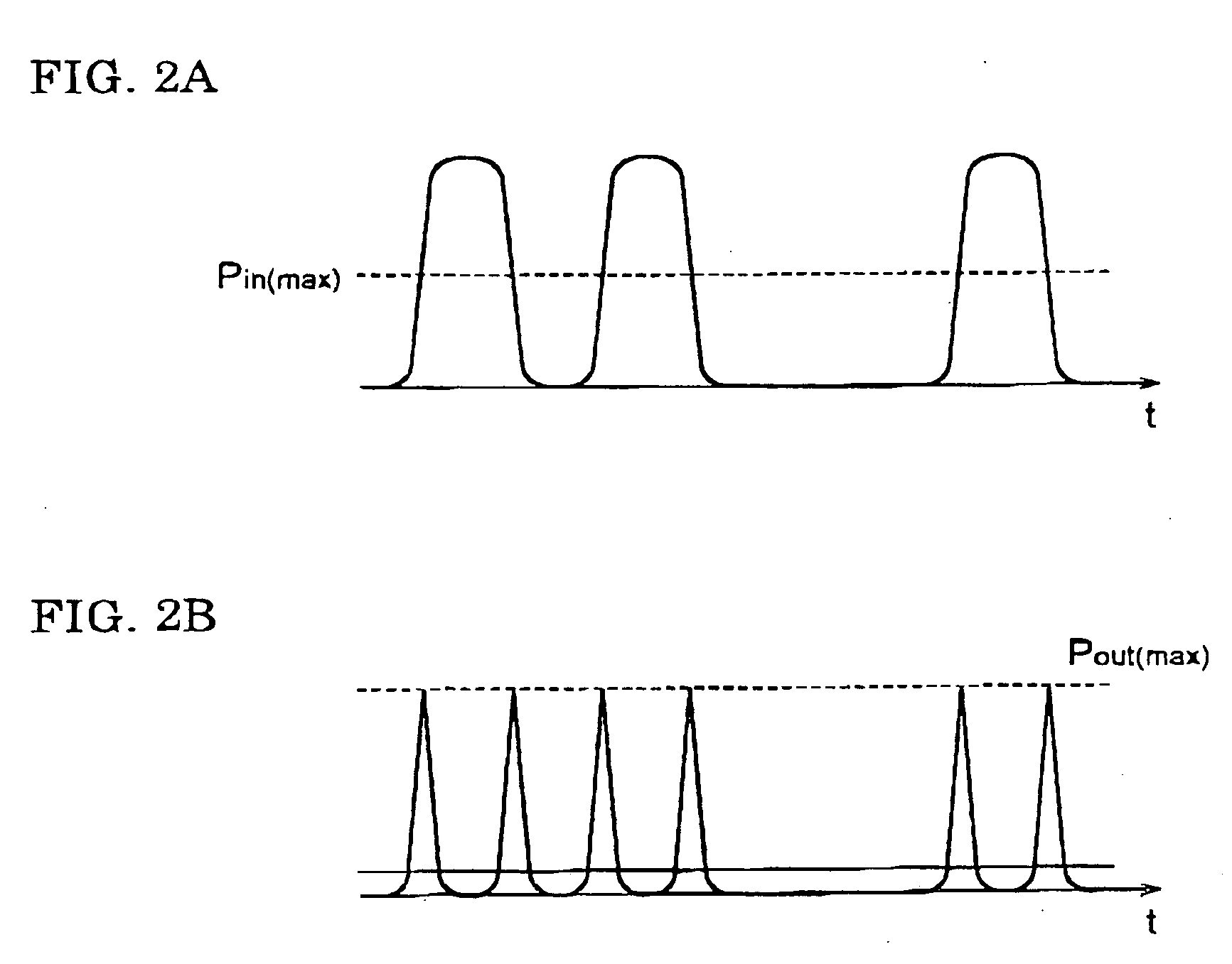
Figure 3
Abstract
Description
BACKGROUND OF THE INVENTION
[0001] 1. Field of the Invention
[0002] The present invention relates to a signal-quality evaluation device for evaluating the quality of optical signals, a signal adjustment method, and an optical-signal evaluation system and an optical transmission system which are equipped with such signal-quality evaluation device.
[0003] 2. Description of the Related Art
[0004] In a future optical transmission system, an optimal condition for transmitting optical signals will tend to change according to the system structure that becomes more complicated due to an increase in transmission capacity. Therefore, adjustment means (e.g. dispersion compensation means) for constantly optimizing the transmission condition is necessary. Furthermore, in order to utilize such adjustment means effectively, a device that evaluates and monitors the quality of an optical signal is also necessary.
[0005] In order to evaluate the quality of an optical signal, a certain parameter must ...
Examples
Embodiment Construction
[0039] A principle of optical-signal evaluation in a signal-quality evaluation device and a signal adjustment method according to embodiments of the present invention will be described first. FIG. 1A is a block diagram of a signal-quality evaluation device 100 according to an embodiment of the present invention. FIG. 1B is a graph illustrating input-output characteristics of an optical component 110 included in the signal-quality evaluation device 100.
[0040] The signal-quality evaluation device 100 has an optical output detector 120 and the optical component 110 functioning as a converter. The optical component 110 outputs input light by reflecting or transmitting it, and as shown in FIG. 1B, an output optical power Pout is a function of an input optical power Pin, the function Pout(Pin) having at least one maximum point. The function Pout(Pin) may have a plurality of maximum points. The optical output detector 120 detects the time-average power of the light output from the optical...