
Low friction fabric
a technology of low friction and fabric, applied in the field of fabric, can solve the problems of reducing the ability of individuals to detect when their skin has been injured, and reducing the ability of individuals to feel their feet, so as to reduce the likelihood of skin trauma, and reduce the effect of shear for
Patent Information
- Authority / Receiving Office
- US · United States
- Patent Type
- Applications(United States)
- Current Assignee / Owner
- Publication Date
- 2008-05-29
- Estimated Expiration
- Not applicable · inactive patent
Smart Images
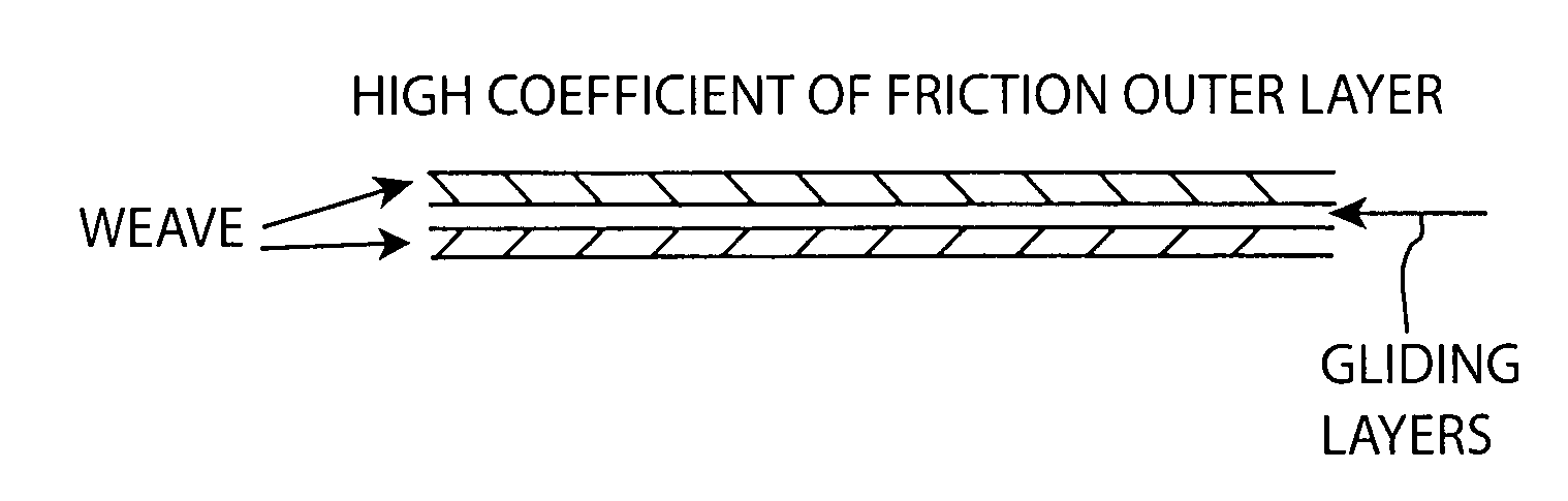
Figure 1 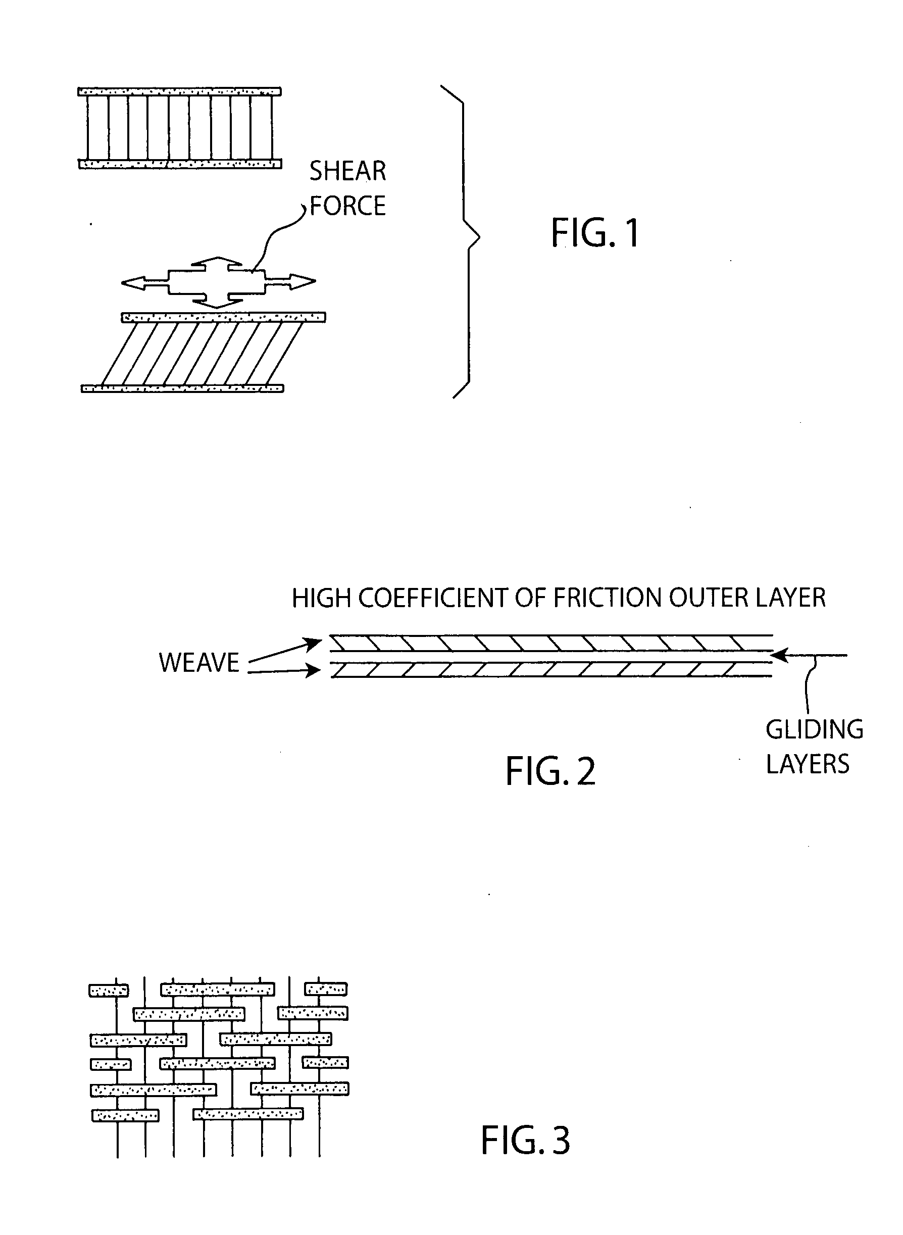
Figure 2 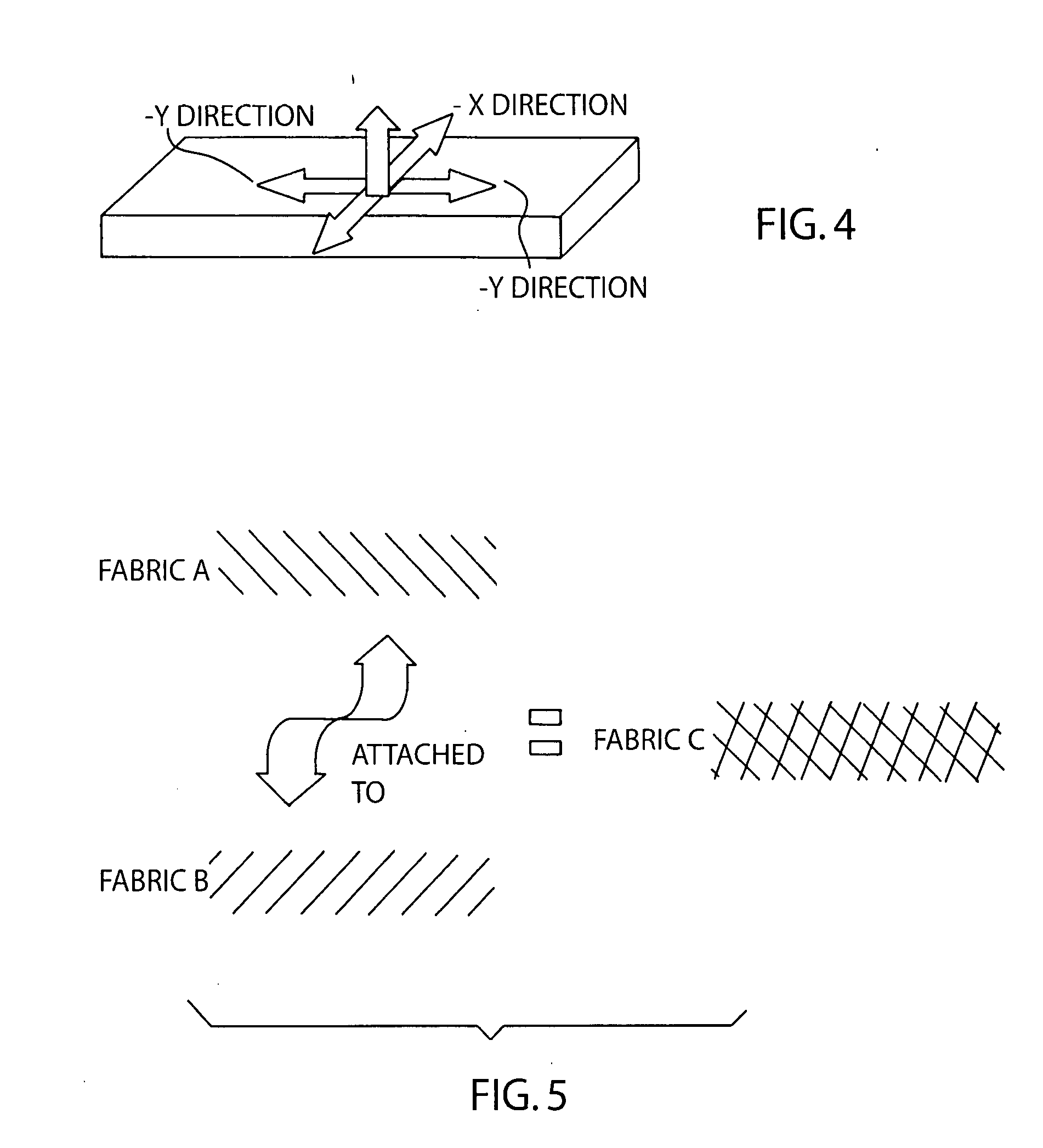
Figure 3
Abstract
Description
RELATED APPLICATIONS
[0001] This application is a Continuation In Part of application Ser. No. 10 / 001,764 filed Jul. 13, 2001, issuing as U.S. Pat. No. 7,281,549 on Oct. 16, 2007.STATEMENT REGARDING FEDERALLY SPONSORED RESEARCH OR DEVELOPMENT
[0002] NoneREFERENCE TO SEQUENCE LISTING, A TABLE OR A COMPUTER PROGRAM LISTING COMPACT DISC APPENDIX
[0003] None.BACKGROUND OF THE INVENTION
[0004] 1. Field of Invention
[0005] This invention relates to a fabric designed to minimize shear forces. It has both medical and recreational applications.
[0006] 2. Background of the Invention
[0007] The formation of calluses is primarily a result of friction. As the layers of skin are loaded in a shearing fashion, the planes of skin separate, leading to blistering in the space between layers. With further progression of shear loads, the upper layer or layers of skin can be traumatized to the point where it separates, leaving a painful, raw, exposed dermis. In addition to the pain associated with dermis exposure, the...
Examples
example i
[0039]The cloth was placed between the heel and a Bertec force plate sampling at 120 Hz. The two components of the shear force is separated into an ±X medial to lateral (side to side) and an ±Y anterior to posterior (front to back) component with respect to the force collection plate. The positive and negative values only indicate direction of the force with respect to the center of the plate as seen in FIG. 4.
[0040]The graph of FIG. 6 shows the shear reactive force being applied across the heel for a period of time with the same fiber rendered in two different alignments. Fibers oriented at zero are aligned while those indicated at 90 are orthogonal to each other. The plot shows movement about the Z axis in the plane formed by X (medial to lateral) and Y (anterior to posterior) axes. Note that shear forces are minimized when fibers are oriented orthogonally.
example ii
[0041]Using a TMI (Testing Machines Inc.) Model 32-06 Slip Friction Tester was calibrated and was running in an environment of 72 degrees Fahrenheit at 40% humidity. The following test was performed:
[0042]An 8.5-cm by 33-cm sample of the fiber was fixed to the bed of the test unit. A 6.5-cm by 6.5-cm sample of the fiber was then fixed to the sled of the test unit with the fibers oriented in the same direction as the fibers on the test bed of the unit. This was designated as a 0 (zero) degree orientation. A test for static and dynamic coefficients of friction was then performed according to the ASTM D 1894 protocol. The static measurement is a reflection of the larger frictional forces during the initiation of motion while the kinetic measurement reflects the friction occurring once the sled was already moving. Thirty tests were performed using the same samples for each test.
[0043]The original sample on the sled was then replaced with a sample of the same fiber type with the directio...