
Quasi-phase matching and quantum control of high harmonic generation in waveguides using counterpropagating beams
a quantum control and waveguide technology, applied in the direction of laser using scattering effects, electrical apparatus, laser details, etc., can solve the problems of significant modulation in both amplitude and phase of harmonics, inability to use hhg, and difficulty in optimizing the modulation period, so as to enhance high-harmonic emission
Patent Information
- Authority / Receiving Office
- US · United States
- Patent Type
- Applications(United States)
- Current Assignee / Owner
- Publication Date
- 2008-06-12
- Estimated Expiration
- Not applicable · inactive patent
Smart Images
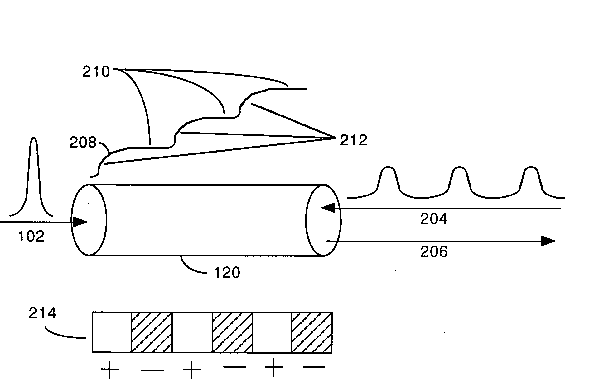
Figure 1 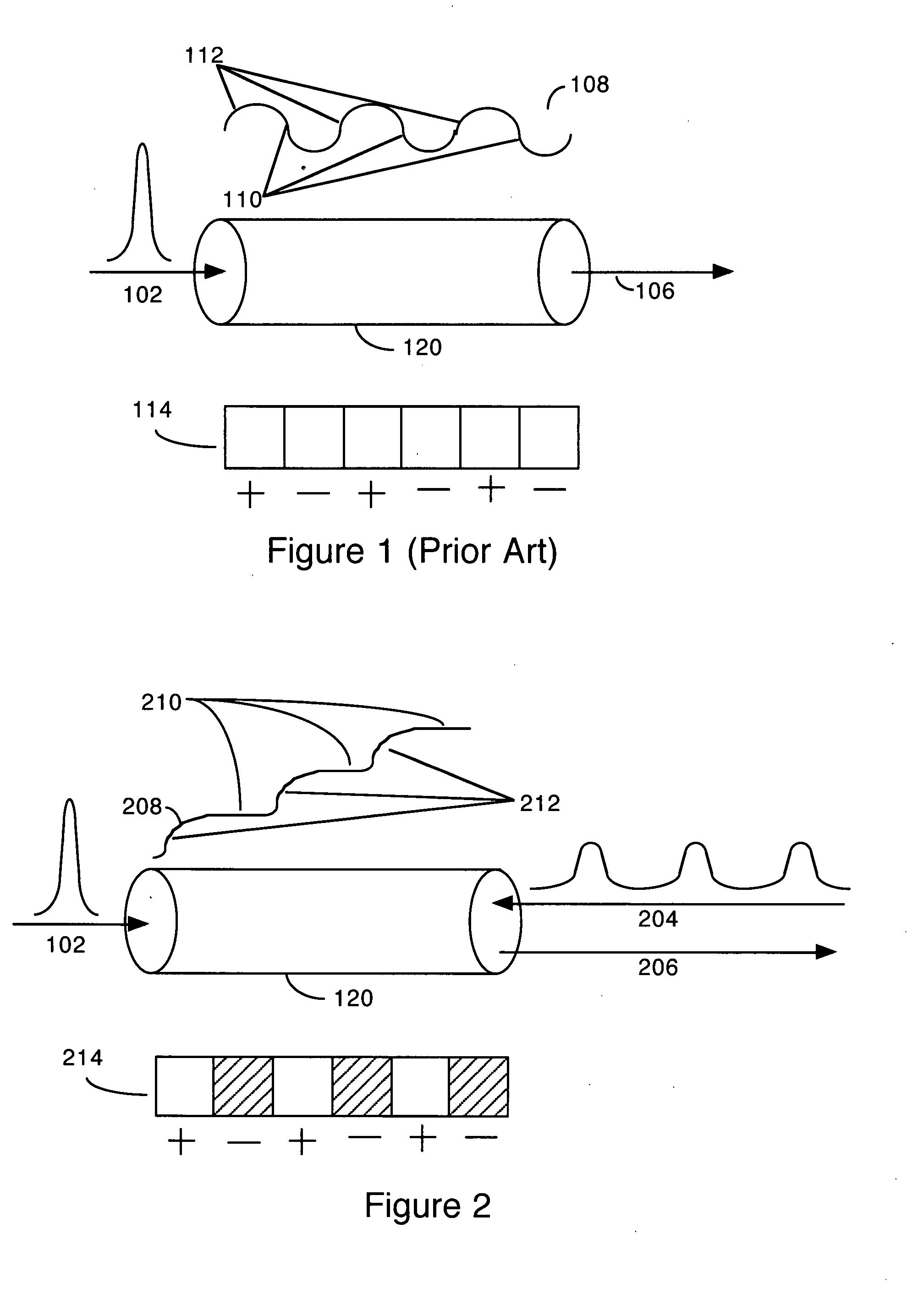
Figure 2 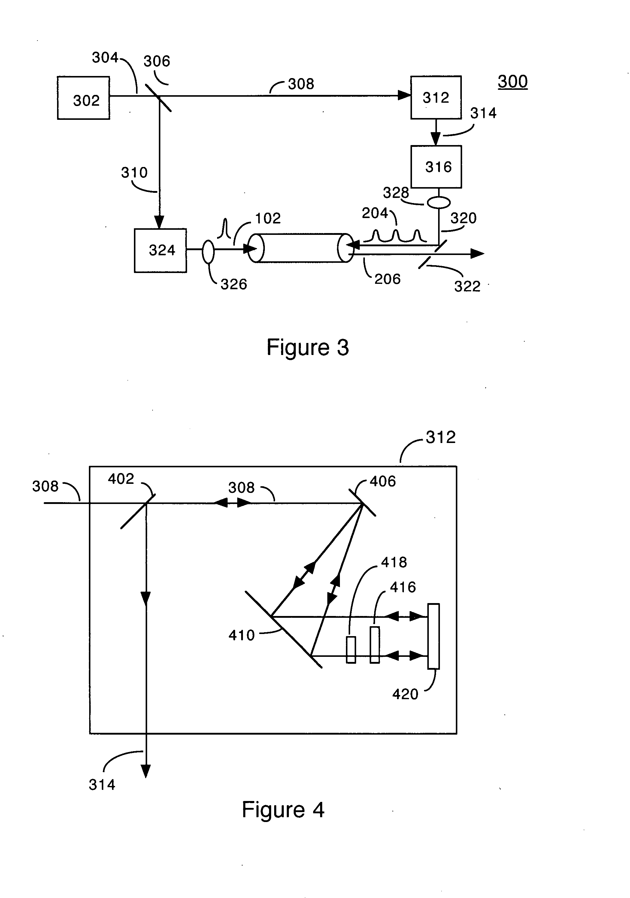
Figure 3
Abstract
Description
PRIORITY
[0001] This application claims benefit of U.S. Provisional Patent Application No. 60 / 835,138, filed Aug. 2, 2006 and incorporates it therein by reference.GOVERNMENT SUPPORT
[0002] The present invention was made with government support as follows, and the U.S. Government has certain rights in the invention.
[0003] National Science Foundation Cooperative Agreement No. EEC-0310717, “NSF Engineering Research Center in Extreme Ultraviolet Science and Technology.”
[0004] Department of Energy, National Nuclear Security Administration, Grant No. DE-FG52-06NA26151, “Investigations of Laser Materials Interactions using Ultrafast Short-Wavelength Light.”BACKGROUND OF THE INVENTION
[0005] 1. Field of the Invention
[0006] The present invention relates to high harmonic generation (HHG) using quasi-phase matching (QPM) via counterpropagating pulse trains in waveguides.
[0007] 2. Description of the Prior Art
[0008] High-order harmonic generation (HHG) driven by ultrashort laser pulses is a source of extr...
Examples
Embodiment Construction
[0026]FIG. 1 (Prior Art) is a schematic diagram illustrating high-harmonic emission generation (HHG) in a waveguide where the process is not phase-matched, and without quasi-phase matching. Input pulse 103 comprises a femtosecond laser pulse, which enters hollow waveguide 120. Signal waveform 108 gives a general indication of the amplitude of HHG over the path length of pulse 102 through waveguide 120. Diagram 114 indicates the regions within waveguide 120 in which constructive and destructive interference of HHG emissions will occur, due to the short coherence length of the HHG beam. The areas indicated by a plus (+) are areas of constructive interference, while the areas indicated by a minus (−) are areas of destructive interference. The length of the plus and minus areas is exactly one coherence length.
[0027]Hence, at first the HHG amplitude increases, but as the coherence length is reached destructive interference causes the amplitude to decrease. This process is repeated with a...