
Fluid flow amplifier
a technology of flow amplifier and flow tube, which is applied in the direction of non-positive displacement pumps, circuit elements, thin material processing, etc., can solve the problems of significant loss and energy waste, mediocre performance of air amplifiers, and inability to operate at such pressures, so as to reduce or completely eliminate reverse flow
Patent Information
- Authority / Receiving Office
- US · United States
- Patent Type
- Applications(United States)
- Current Assignee / Owner
- Publication Date
- 2009-02-05
Smart Images
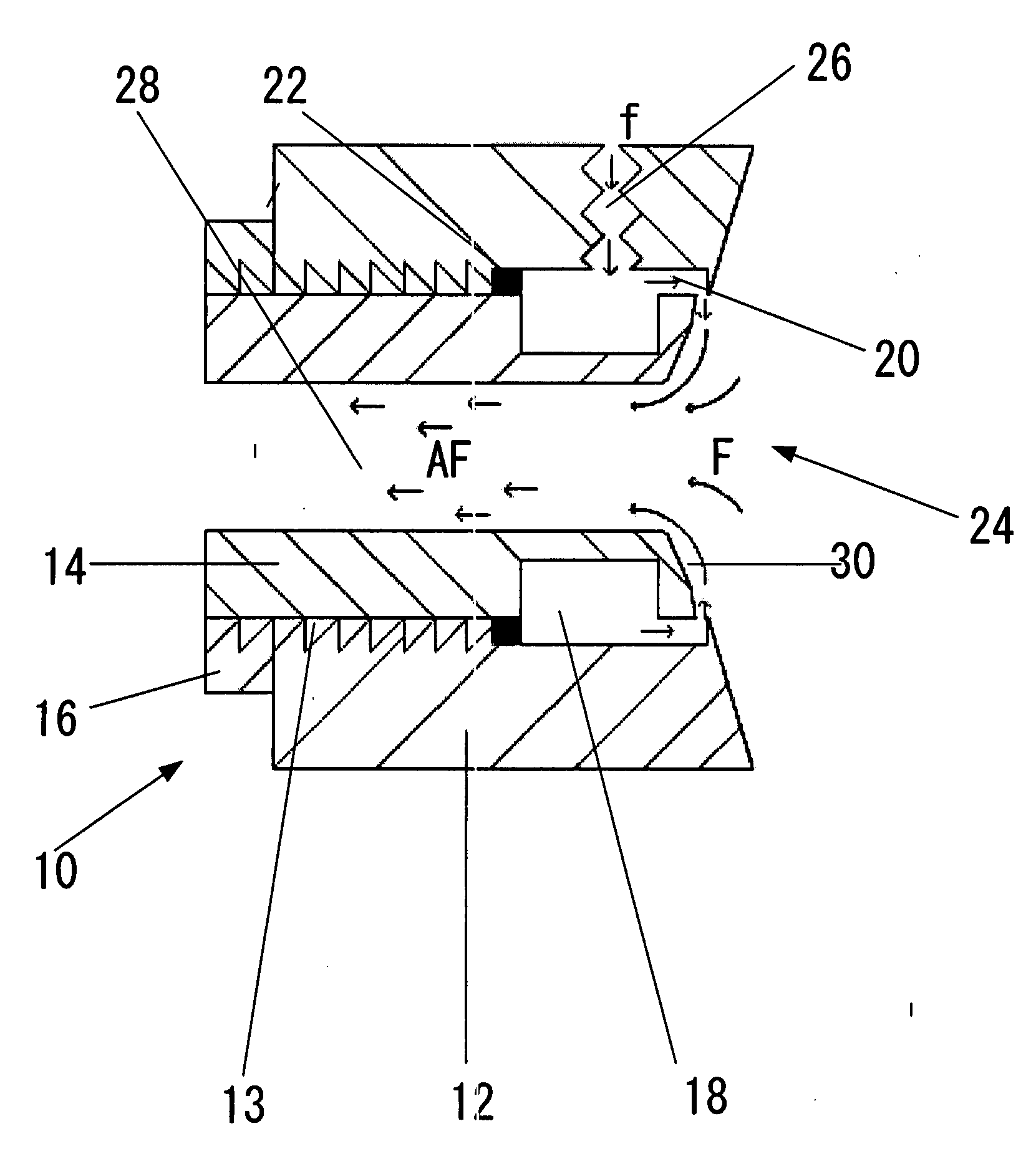
Figure 1 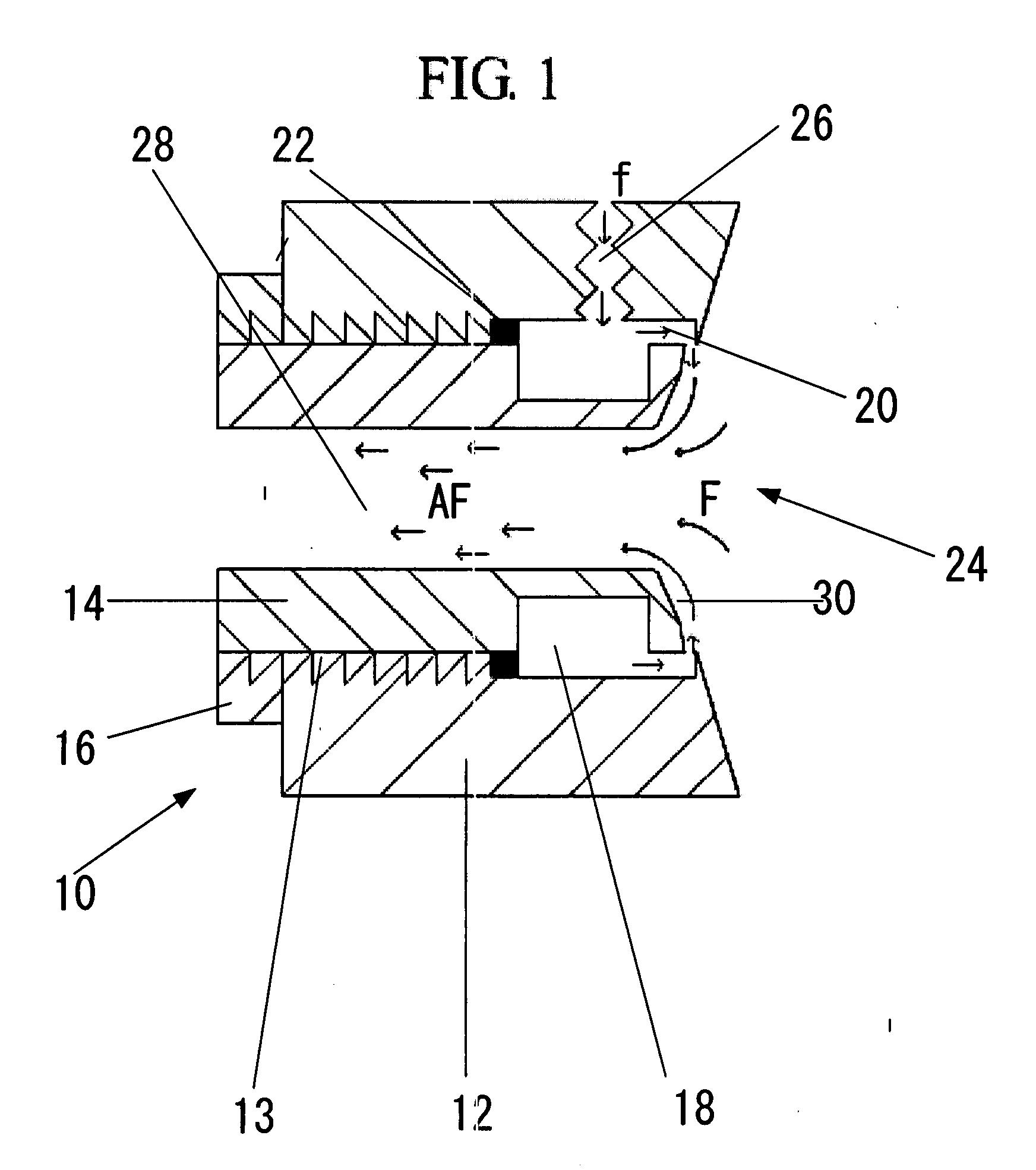
Figure 2 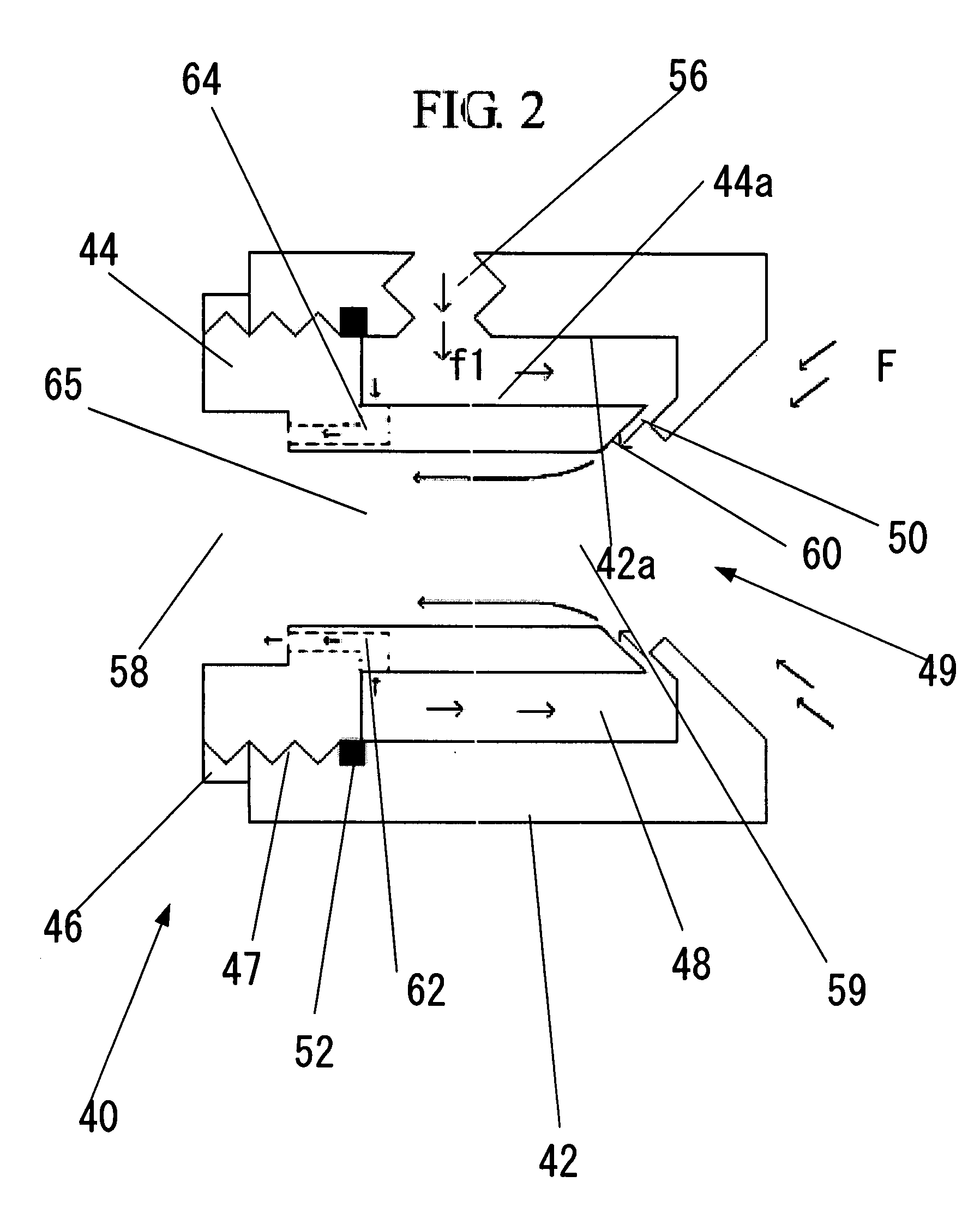
Figure 3
Abstract
Description
FIELD OF INVENTION
[0001] This invention relates to the field of fluid flow amplifiers and in particular to fluid flow amplifiers that can operate at high inlet pressures ranging from 125 psig to 1000 psig+ (8.77 kg / cm2 to 70 kg / cm2) while having maximum air entrainment efficiency, maximum outlet velocity, and resistance to flow reversal and turbulence.BACKGROUND OF INVENTION—PRIOR ART
[0002] Fluid flow amplifiers, which are also called thrust jets or air flow amplifiers when the fluid is air, are pressure velocity transducers that use a small amount of a compressed fluid, e.g., compressed air, as their power source. Normally, such a device consists of two pieces. The first piece is called a body and the second piece is called a plug. The plug typically has a seal ring to seal pressurized air from leaking. The plug is screwed into the body thus forming an annular chamber and a nozzle between the body and the plug. The body has an inlet to which compressed air is introduced. As compresse...
Examples
Embodiment Construction
—PREFERRED EMBODIMENTS
[0037]The inventors herein have developed a fluid flow amplifier that will have the ability to operate at pressures ranging from 8.5 atm (125 psig) to 68 atm (1000+ psig) without flow reversal and turbulence, as what commonly happens in current-art air amplifiers. The use of a by-pass or secondary nozzle assists the primary nozzle such that pressurized airflow discharged from the primary nozzle is forced to flow to the rear of the air amplifier as smoothly as possible. The benefit a secondary nozzle is that it allows for obtaining high energy air flows needed for a turbomachine to acquire supersonic tip speeds.
[0038]FIG. 2 is a view of an arrangement according to one embodiment of the present invention that illustrates a fluid flow amplifier with a by-pass or secondary nozzle. The arrangement shown in FIG. 2 consists essentially of an air amplifier 40 having a body 42, and a plug 44 connected to an amplifier body 42, e.g., by means of a threaded connection 47, ...