
High Voltage Power Supply
a high-voltage power supply and power supply technology, applied in the direction of power conversion systems, dc-dc conversion, instruments, etc., can solve the problems of inefficiency and waste of output voltage, performance decline, etc., and achieve the effect of effective regulation of the voltage of the power source applied
Patent Information
- Authority / Receiving Office
- US · United States
- Patent Type
- Applications(United States)
- Current Assignee / Owner
- Publication Date
- 2009-12-24
- Estimated Expiration
- Not applicable · inactive patent
Smart Images
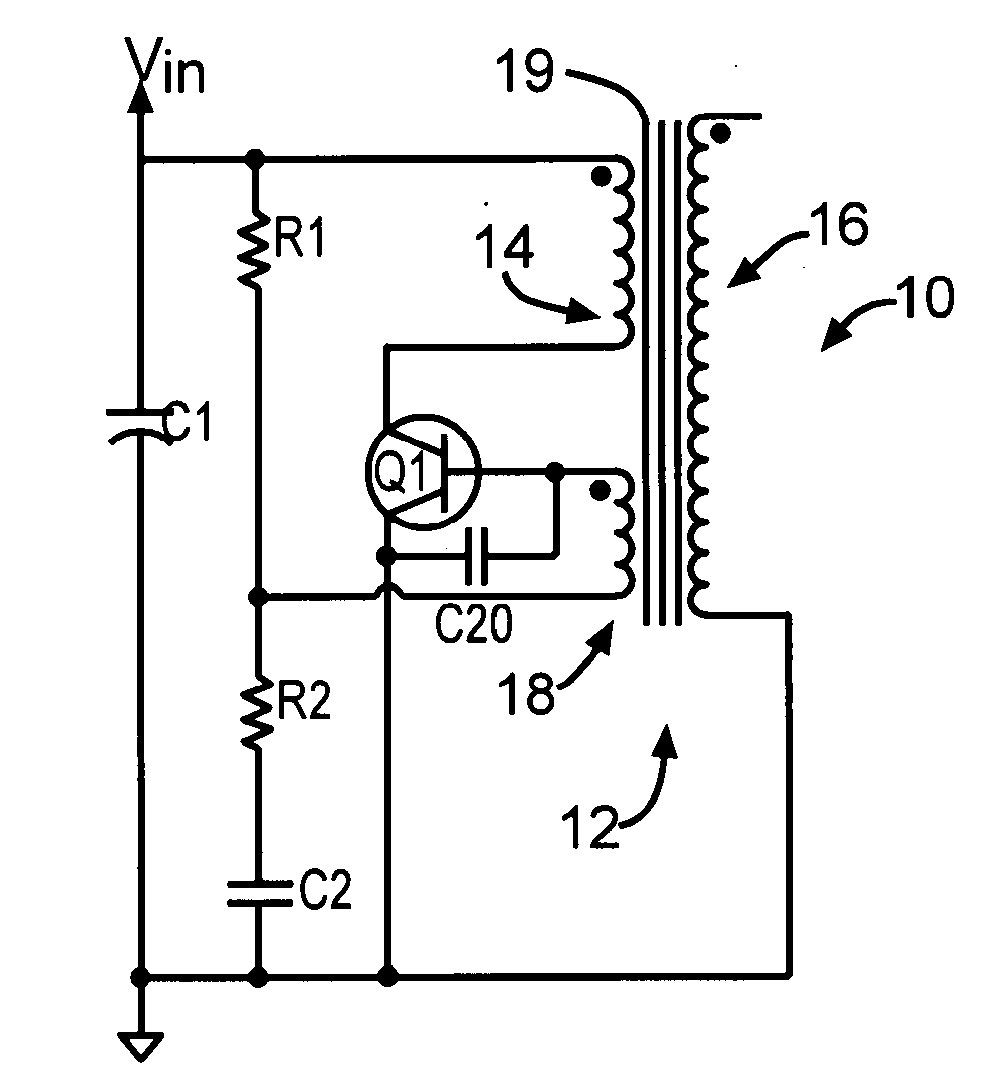
Figure 1 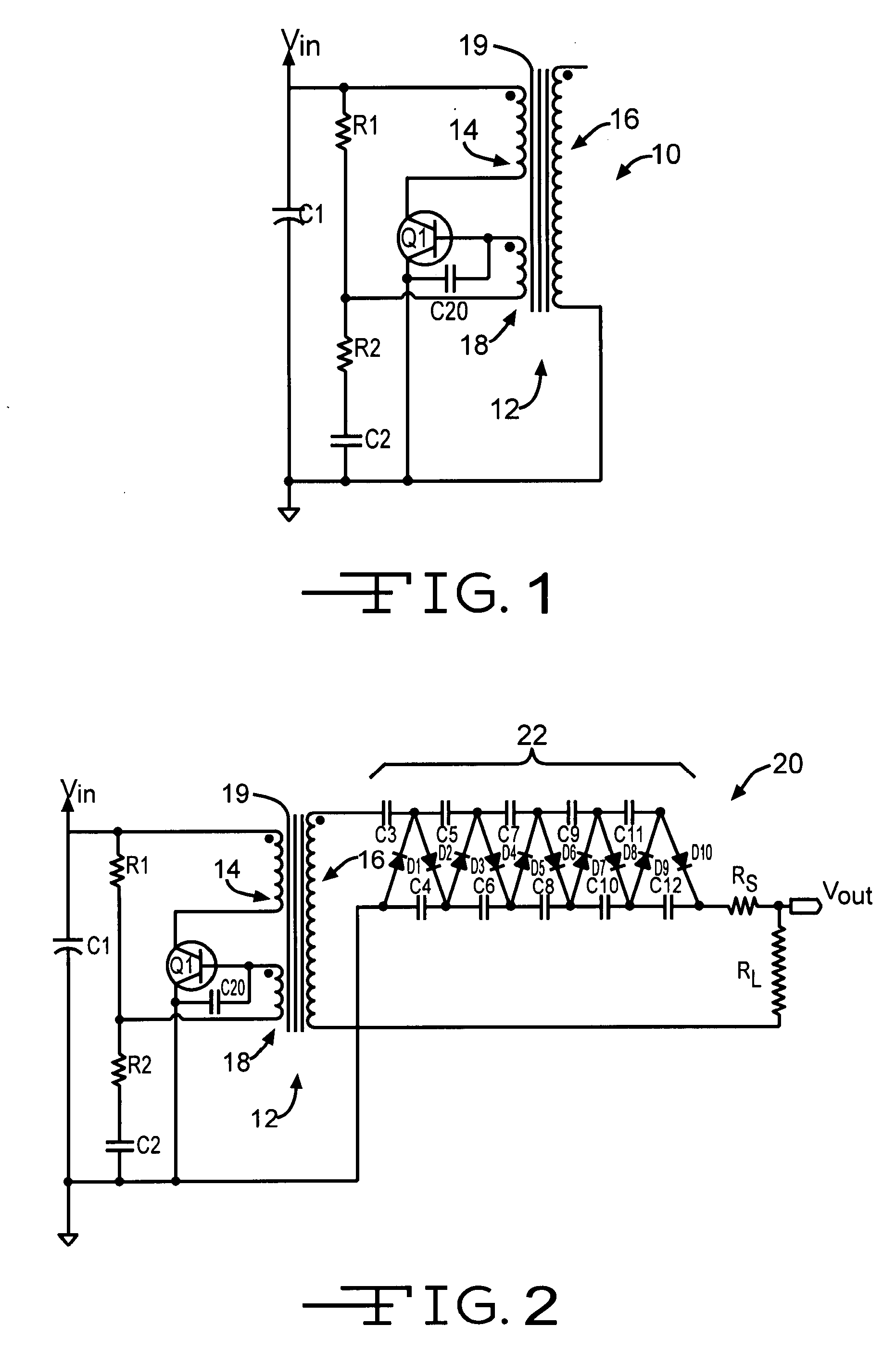
Figure 2 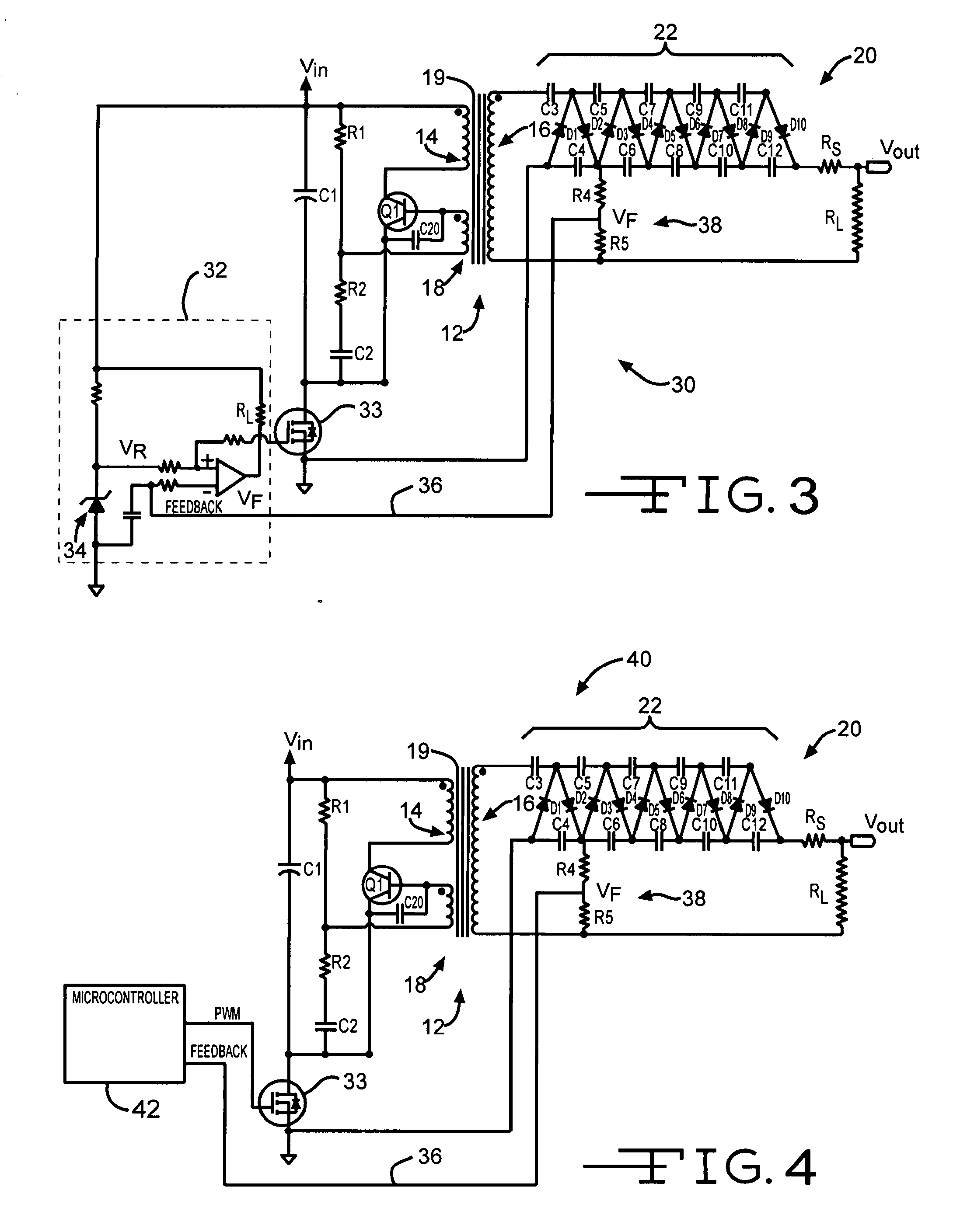
Figure 3
Abstract
Description
BACKGROUND OF THE INVENTION
[0001] This invention relates in general to the control of high voltage power supplies, and in particular to consistent control of high voltage power from low voltage sources.
[0002] A High Voltage Power Supply (HVPS) commonly provides inconsistent output voltage which is inefficient and wasteful. This is particularly true when the HVPS is powered by a source such as batteries, which decline in performance over time. A consistent, high output voltage which is low cost and efficient is desired. Low cost, efficient, consistent and compact high voltage components are particularly desired for commercial applications, and in particular for electro-hydrodynamic spraying of materials.SUMMARY OF THE INVENTION
[0003] This invention relates to consistent control of high voltage power from low voltage sources.
[0004] The present invention contemplates a High Voltage Power Supply (HVPS) that includes a flyback transformer having a primary winding and a feedback winding, the ...
Examples
examples
[0041]Referring now to the circuit HVPS 20 of FIG. 2, the inventors tested the circuit with a compensating capacitor C20 having a value of 0.033 uF. An oscilloscope screen of the transistor Q1 voltages is shown in FIG. 9, where the top trace is the collector signal monitored at point (a) and the bottom trace is the base signal at point (b). The compensating capacitor C20 was then removed and the test repeated, with the results shown in FIG. 10. It is clear that with the inclusion of the compensating capacitor C20, the amount of ripple was significantly reduced in the base signal (b) as well as in collector signal (a). More importantly, input current to the converter, which was at a fixed 4-volt input voltage, was reduced from 116 milliamperes (mA) to 99 mA, or by 14.66%, while the output voltage into a fixed impedance decreased from 24.4 kilovolts (kV) to 22.7 kV, or by 6.97%. Since the input voltage VIN was the same for both cases, the decrease in input current indicates a reduced ...