

High speed ball shear machine
Patent Information
- Authority / Receiving Office
- US · United States
- Current Assignee / Owner
- Publication Date
- 2010-12-02
Smart Images
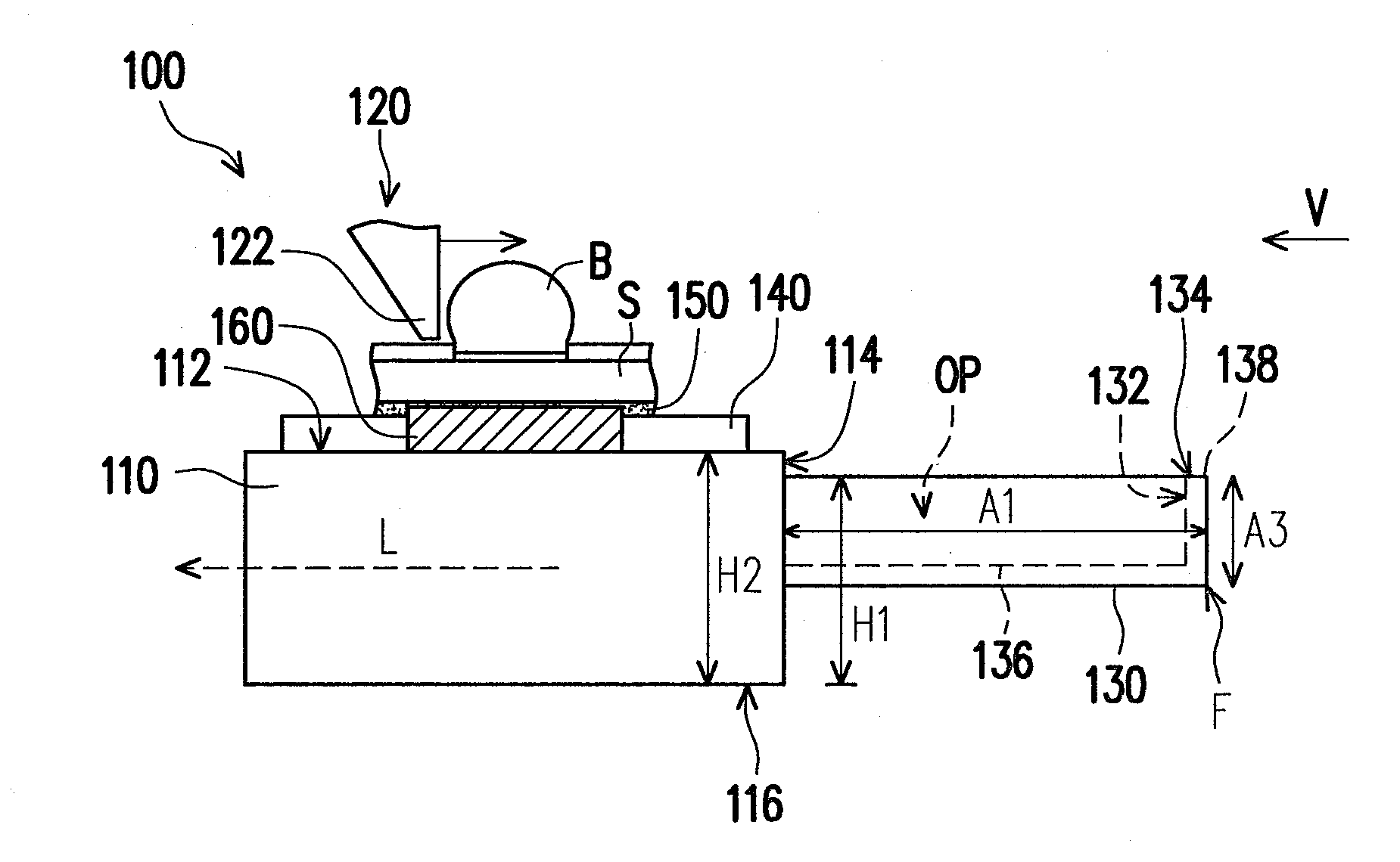
Figure 1 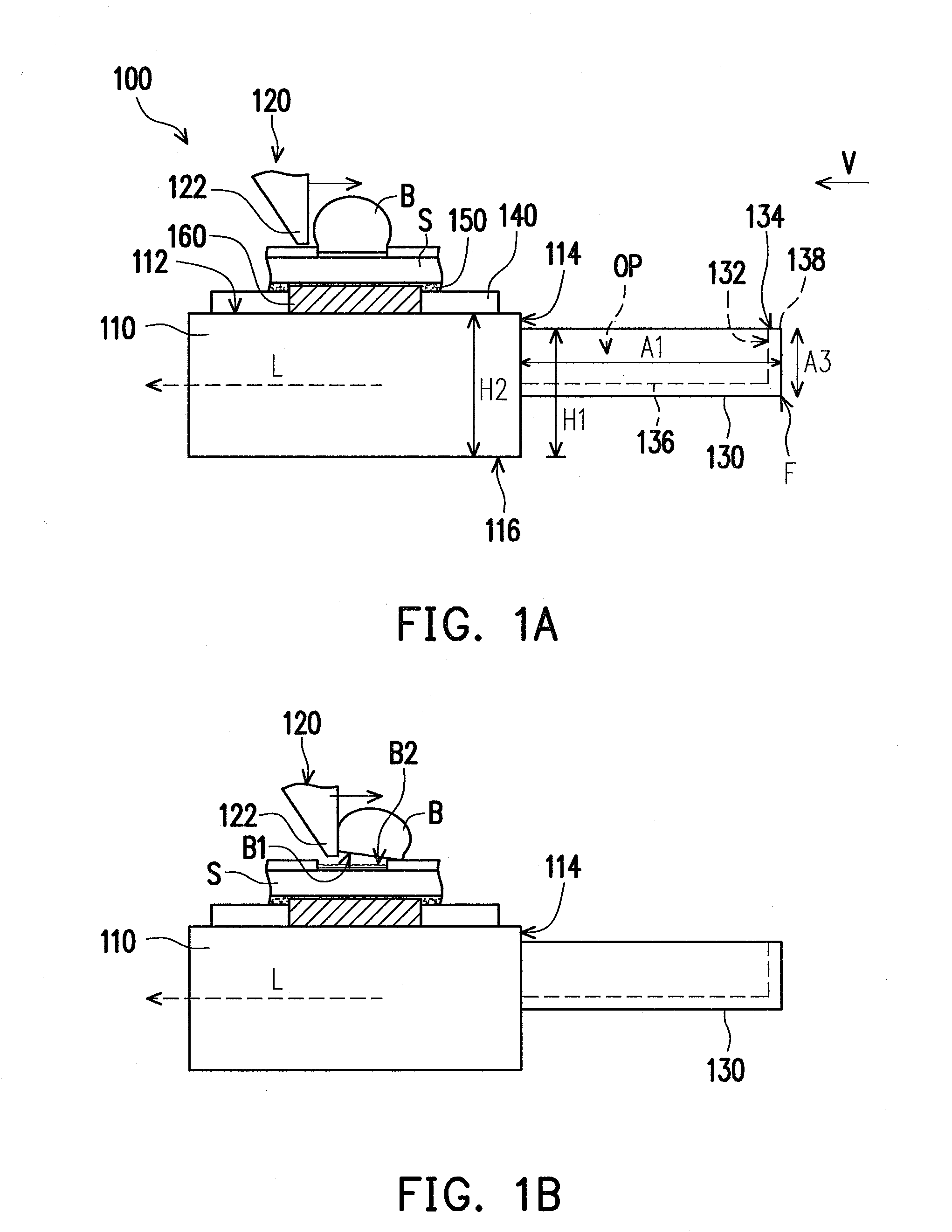
Figure 2 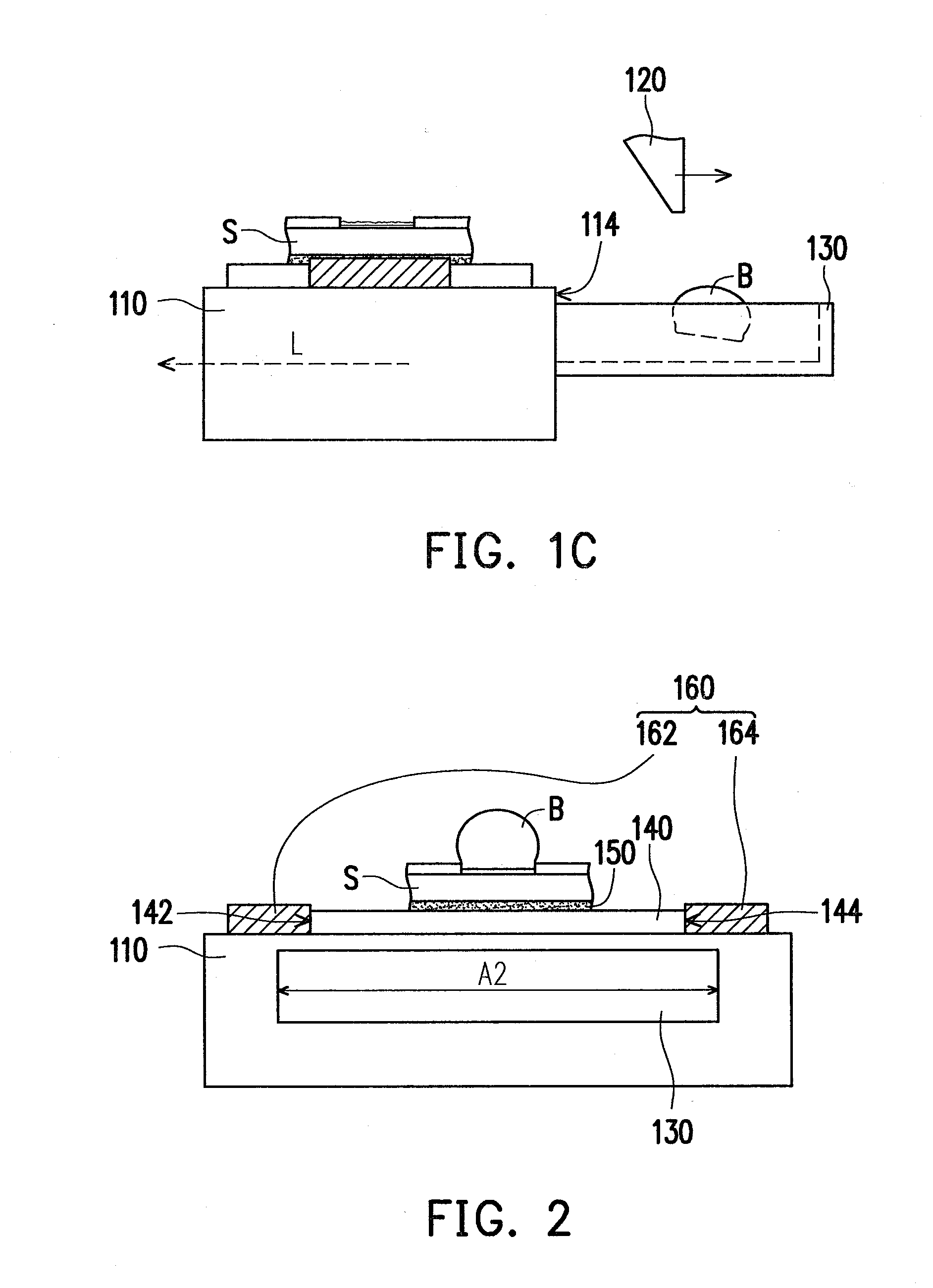
Figure 3
Abstract
Description
CROSS-REFERENCE TO RELATED APPLICATION
[0001] This application claims the priority benefit of Taiwan application serial no. 98118041, filed Jun. 1, 2009. The entirety of the above-mentioned patent application is hereby incorporated by reference herein and made a part of specification.BACKGROUND OF THE INVENTION
[0002] 1. Field of the Invention
[0003] The present invention relates to a high speed ball shear machine, and more particularly to a high speed ball shear machine capable of collecting dropping metal bumps.
[0004] 2. Description of Related Art
[0005] Soldering is a key process for manufacturing solder joints, which is to apply an alloy with a lower melting point to joint two opposite materials together. The functions of solder joints are not only adopted as signal and electrical power passages between the devices, but also as the mechanical support during devices operation. According to recent International Roadmap for Semiconductor Technology announced by the Semiconductor Industry As...
Examples
Embodiment Construction
[0032]FIGS. 1A through 1C are schematic diagrams illustrating a high speed ball shear machine in a ball shearing process according to one embodiment of the present invention. FIG. 2 is a schematic diagram illustrating a fixing base and a metal bump catcher of the high speed ball shear machine in FIG. 1A from a direction V. FIG. 3 and FIG. 5 are respectively schematic diagrams of two variation structures of the high speed ball shear machine in FIG. 1A. FIG. 4 is a schematic diagram illustrating a fixing base and a metal bump catcher of the high speed ball shear machine in FIG. 3 from a direction V. FIG. 6 is a schematic diagram illustrating a fixing base and a metal bump catcher of the high speed ball shear machine in FIG. 5 from a direction V.
[0033]Referring to FIG. 1A and FIG. 2 simultaneously, a high speed ball shear machine 100 of the present embodiment is adapted to remove a metal bump B fixed on a substrate S. Here, the metal bump B is an aluminum ball, for example. The high sp...