
Motor drive system using potential at neutral point
a technology of motor drive and neutral point, applied in the direction of motor/generator/converter stopper, dynamo-electric gear control, dynamo-electric converter control, etc., to achieve the effect of reducing the ripple appearing in the output torqu
Patent Information
- Authority / Receiving Office
- US · United States
- Patent Type
- Applications(United States)
- Current Assignee / Owner
- Publication Date
- 2010-12-23
Smart Images
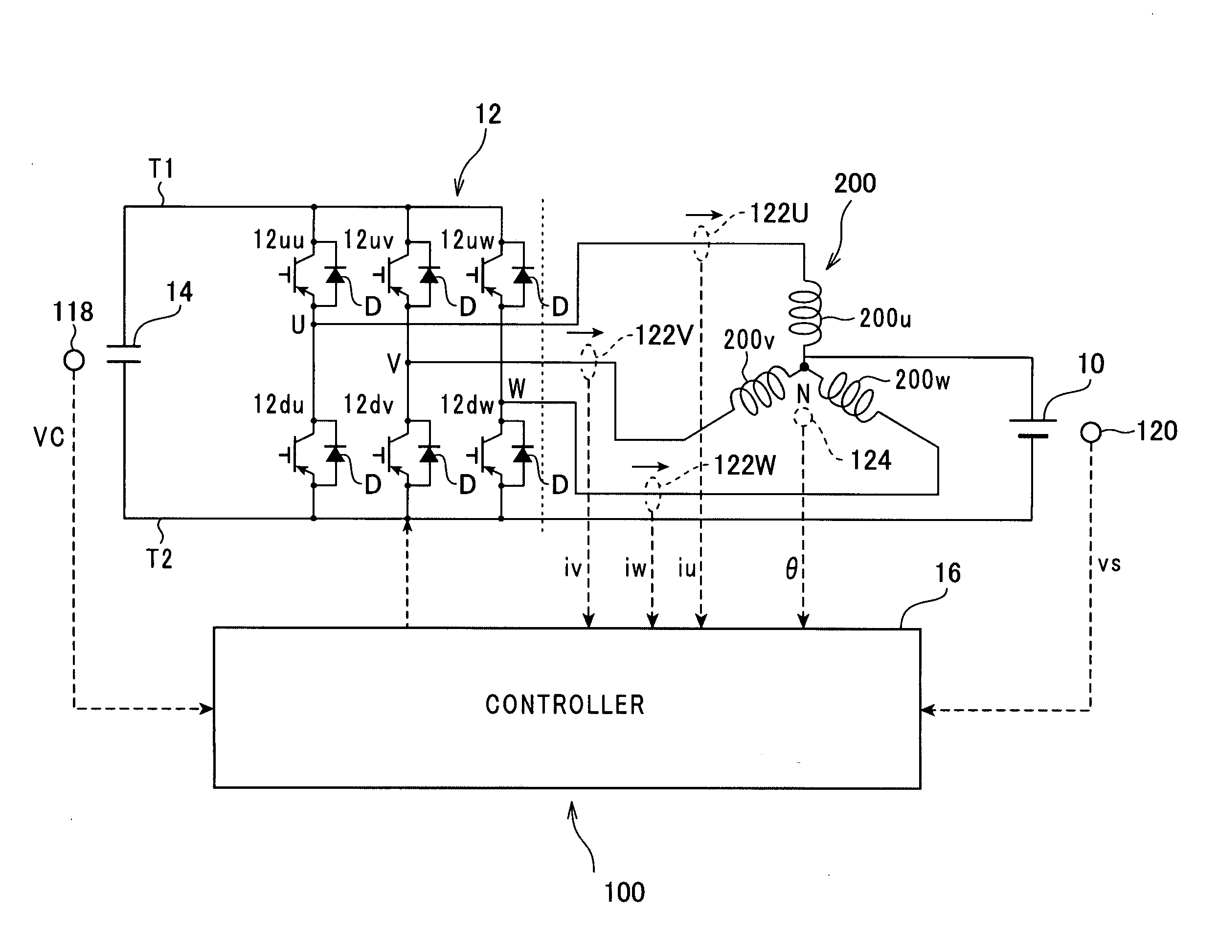
Figure 1 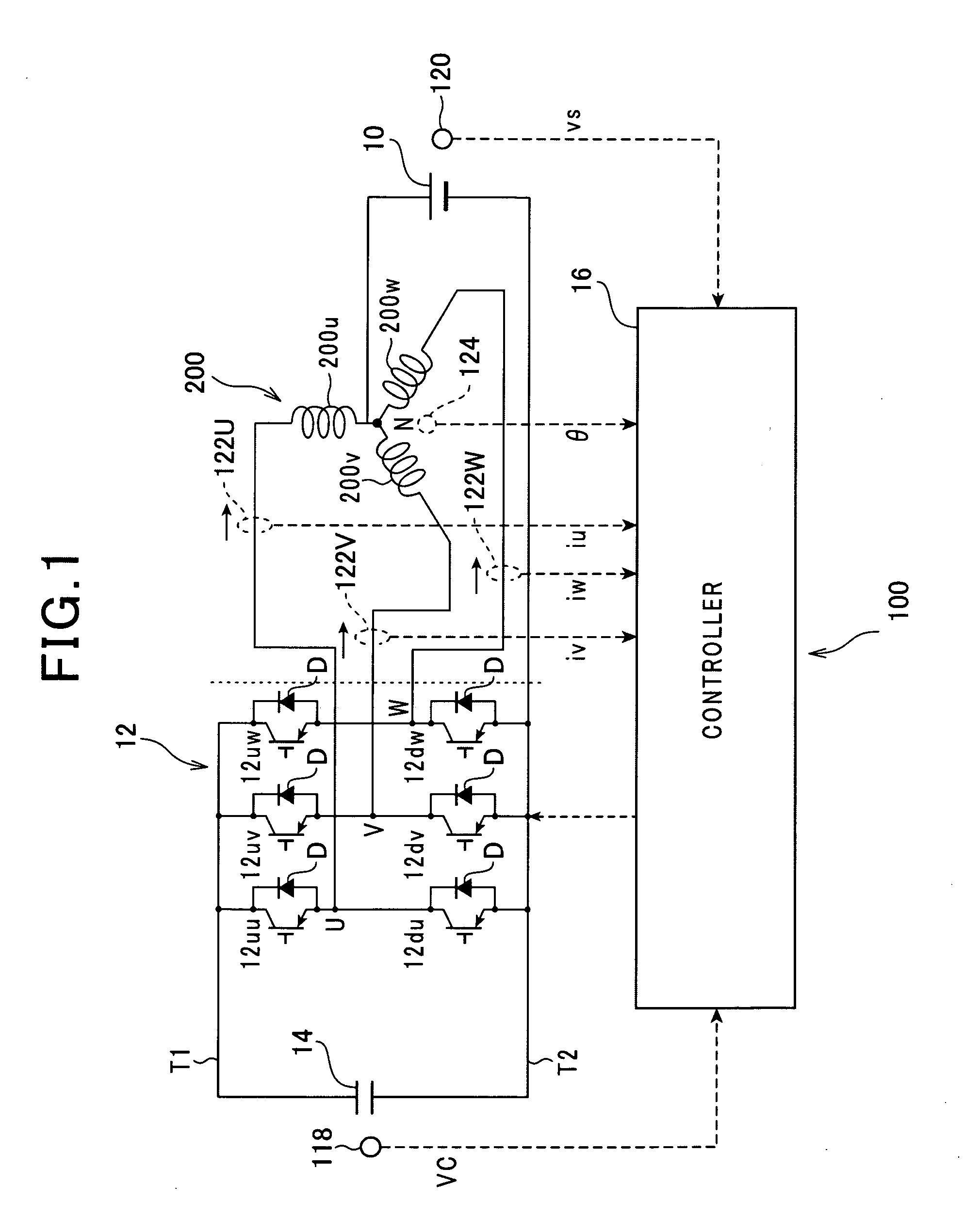
Figure 2 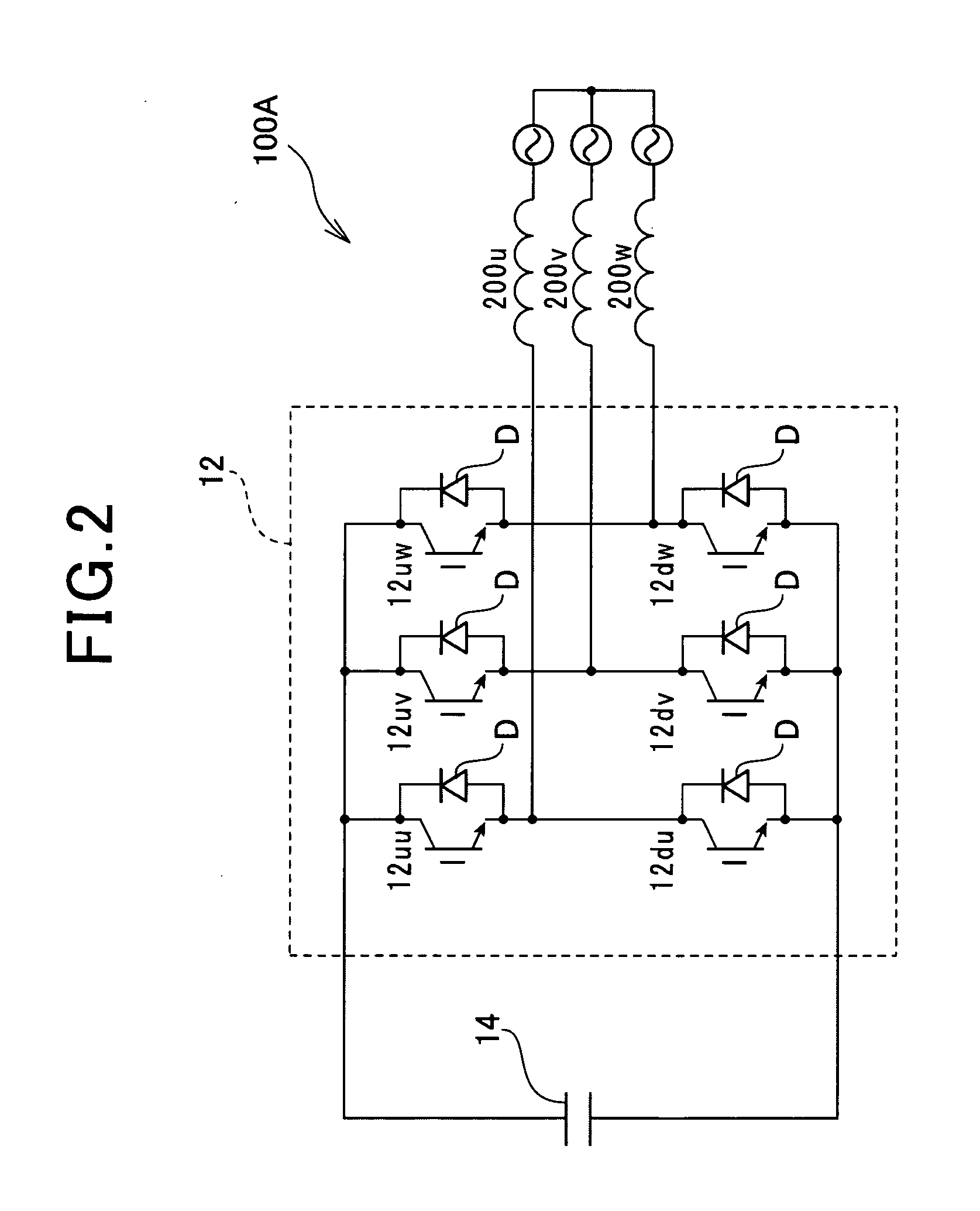
Figure 3
Abstract
Description
CROSS REFERENCE TO RELATED APPLICATIONS
[0001] This application is based on Japanese Patent Application 2009-147970 filed on Jun. 22, 2009. The descriptions of the Patent Application are all incorporated herein by reference,FIELD OF THE INVENTION
[0002] The present invention relates to motor drive systems with star-connected multiphase stator windings, and, more particularly, to such motor drive systems that control a motor using the potential at a neutral point of the star-connected multiphase stator windings.BACKGROUND OF THE INVENTION
[0003] Motor drive systems with secondary batteries are used in electric vehicles, hybrid vehicles, railways, or other machines. Such motor drive systems include an inverter that converts direct current into alternating current, and apply the alternating current to an AC (Alternating Current) motor, such as a brushless motor, to thereby drive the motor. These motor drive systems normally use a converter for boosting a battery voltage, and apply the booste...
Examples
Embodiment Construction
[0028]An embodiment of the present invention will be described hereinafter with reference to the accompanying drawings.
[0029]Referring to FIG. 1, there is provided a motor drive system 100 for a three-phase AC motor 200 according to this embodiment of the present invention.
[0030]The three-phase AC motor 200 is comprised of a rotor (not shown), a stator core, and star connected three-phase stator windings 200U, 200V, and 200W wound in the stator core.
[0031]For example, the rotor is provided at its circumferential portions with at lest one pair of permanent magnets. The permanent magnets of the at least one pair are so embedded in the outer periphery of the rotor core as to be symmetrically arranged with respect to the center axis of the rotor at regular intervals in a circumferential direction of the rotor core.
[0032]One permanent magnet of the at least one pair has a north pole (N pole) directed radially outward away from the center of the rotor. The other permanent magnet has a sou...