
Ripple compensation method and apparatus
a compensation method and a technology of ripple compensation, applied in the direction of process and machine control, instruments, can solve the problems of unfavorable lighting system overall energy efficiency improvement, inability to operate directly, and undesired drive current fluctuations, so as to reduce ripple
Patent Information
- Authority / Receiving Office
- US · United States
- Patent Type
- Applications(United States)
- Current Assignee / Owner
- Publication Date
- 2008-02-21
- Estimated Expiration
- Not applicable · inactive patent
Smart Images
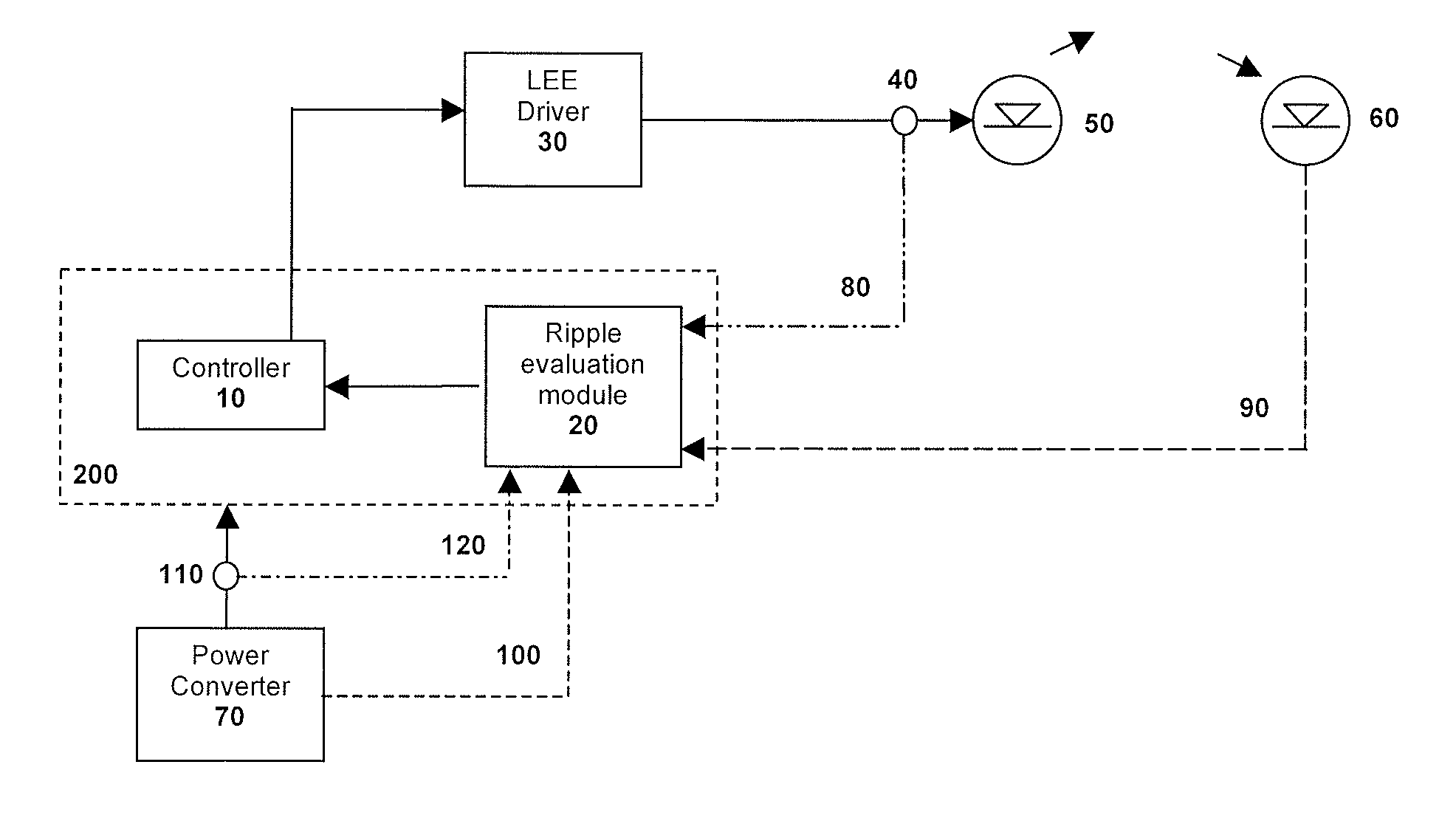
Figure 1 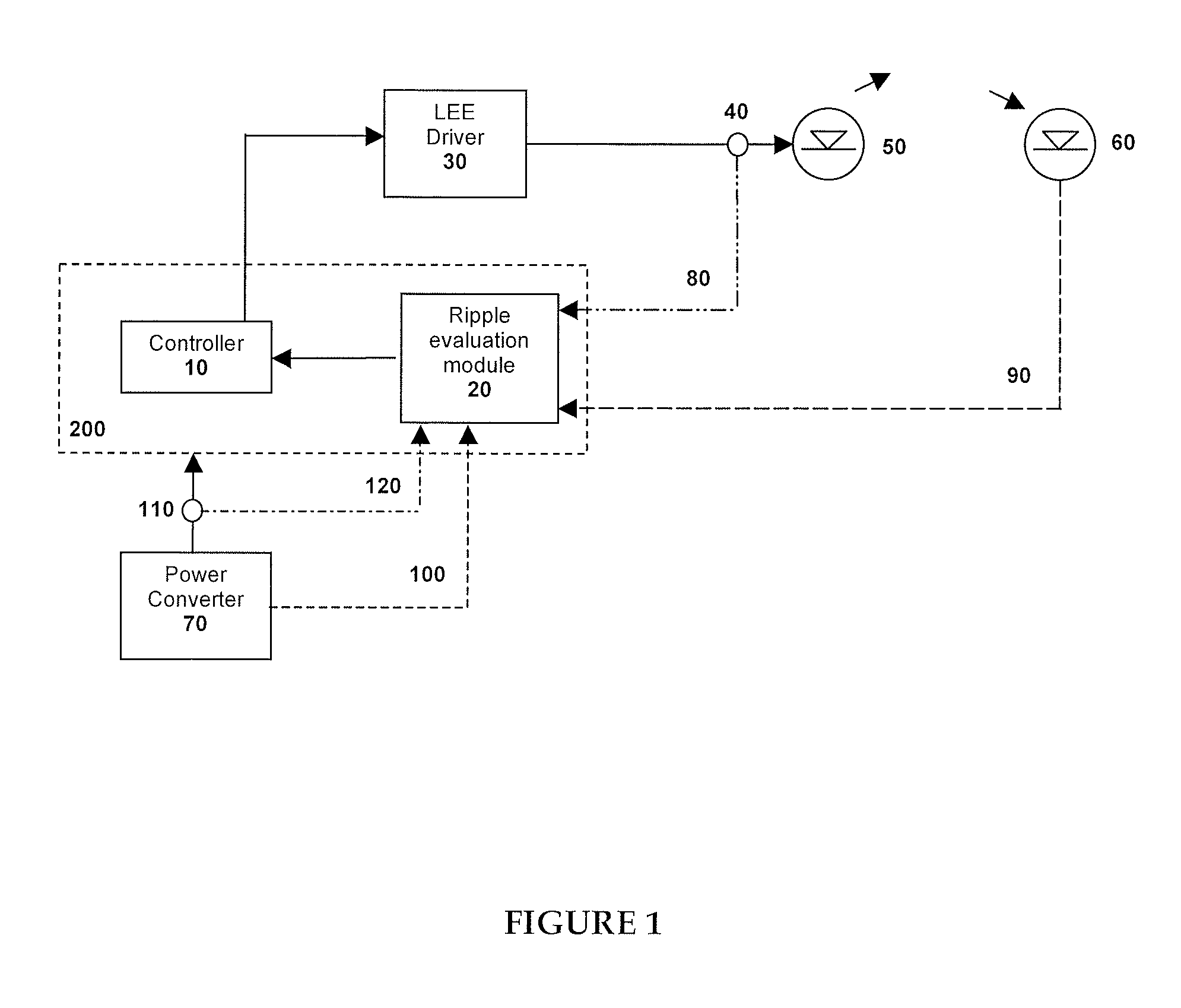
Figure 2 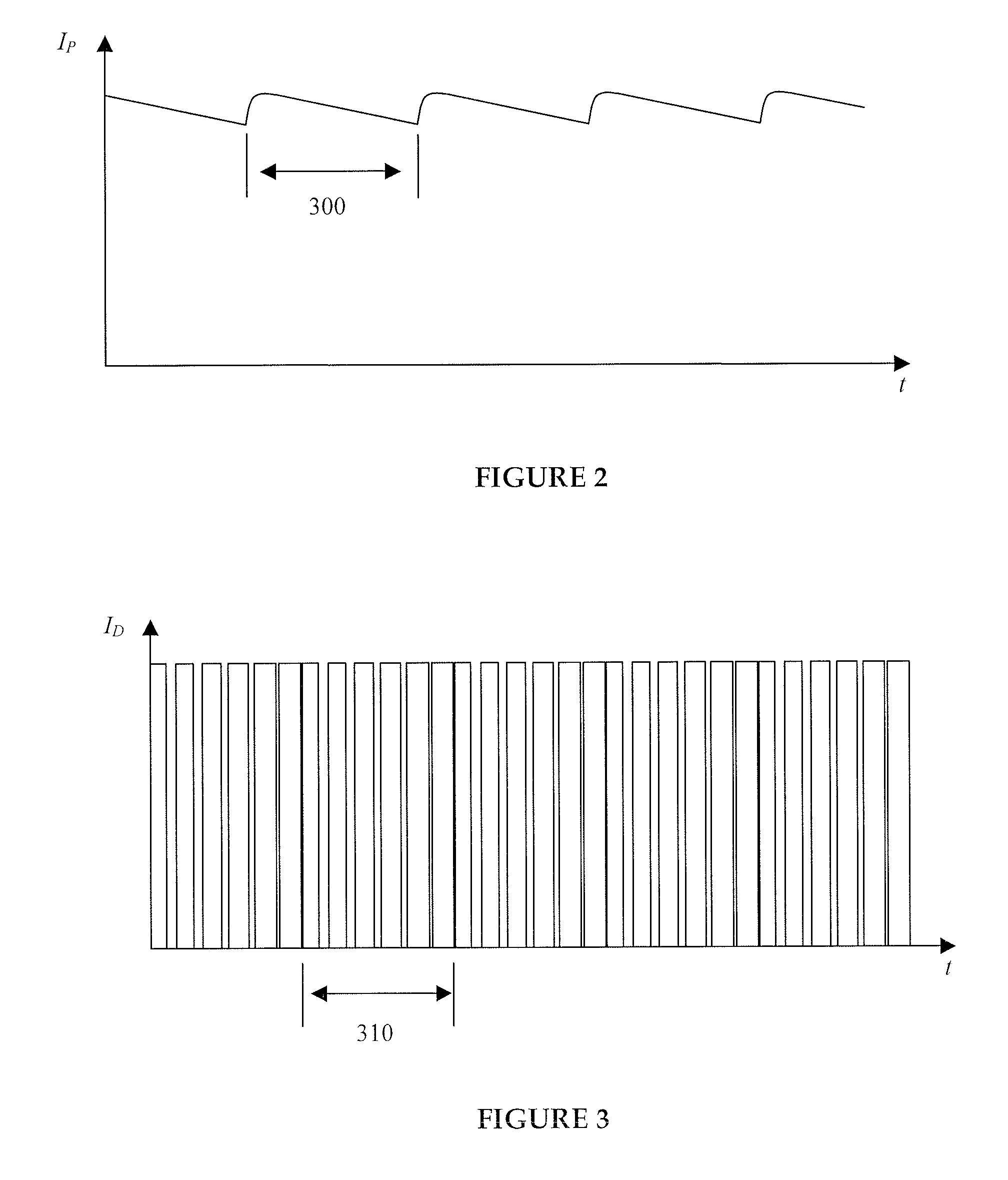
Figure 3
Abstract
Description
CROSS REFERENCE TO RELATED APPLICATIONS
[0001] This application claims the benefit of U.S. Provisional Application Ser. No. 60 / 839,063, filed on Aug. 21, 2006, herein incorporated by reference in its entirety.FIELD OF THE INVENTION
[0002] The present invention pertains to illumination systems and in particular it pertains to drive current ripple compensation for LED type illumination systems.BACKGROUND OF THE INVENTION
[0003] Inorganic and organic semiconductor light-emitting diodes (LEDs) have been successfully used in illumination applications, including architectural, entertainment, and roadway lighting, for example. Light-emitting diode based luminaries often require specific forms of electrical power and cannot be operated directly with the forms of electricity which are provided by power grids. The amount of light emitted by LEDs depends on the LED drive current. The brightness of LEDs follows changes in the drive current in a transient fashion with delay times of typically 10−7 sec...
Examples
Embodiment Construction
Definitions
[0014]The term “ripple” is used to define a form of residual harmonic content of a DC voltage or DC current signal at the output of a power converter.
[0015]The term “light-emitting element” (LEE) is used to define a device that emits radiation in a region or combination of regions of the electromagnetic spectrum for example, the visible region, infrared and / or ultraviolet region, when activated by applying a potential difference across it or passing a current through it, for example. Therefore a light-emitting element can have monochromatic, quasi-monochromatic, polychromatic or broadband spectral emission characteristics. Examples of light-emitting elements include semiconductor, organic, or polymer / polymeric light-emitting diodes, optically pumped phosphor coated light-emitting diodes, optically pumped nano-crystal light-emitting diodes or other similar devices as would be readily understood by a worker skilled in the art. Furthermore, the term light-emitting element is...