

Mop Press
Patent Information
- Authority / Receiving Office
- US · United States
- Current Assignee / Owner
- Publication Date
- 2011-03-10
- Estimated Expiration
- Not applicable · inactive patent
Smart Images
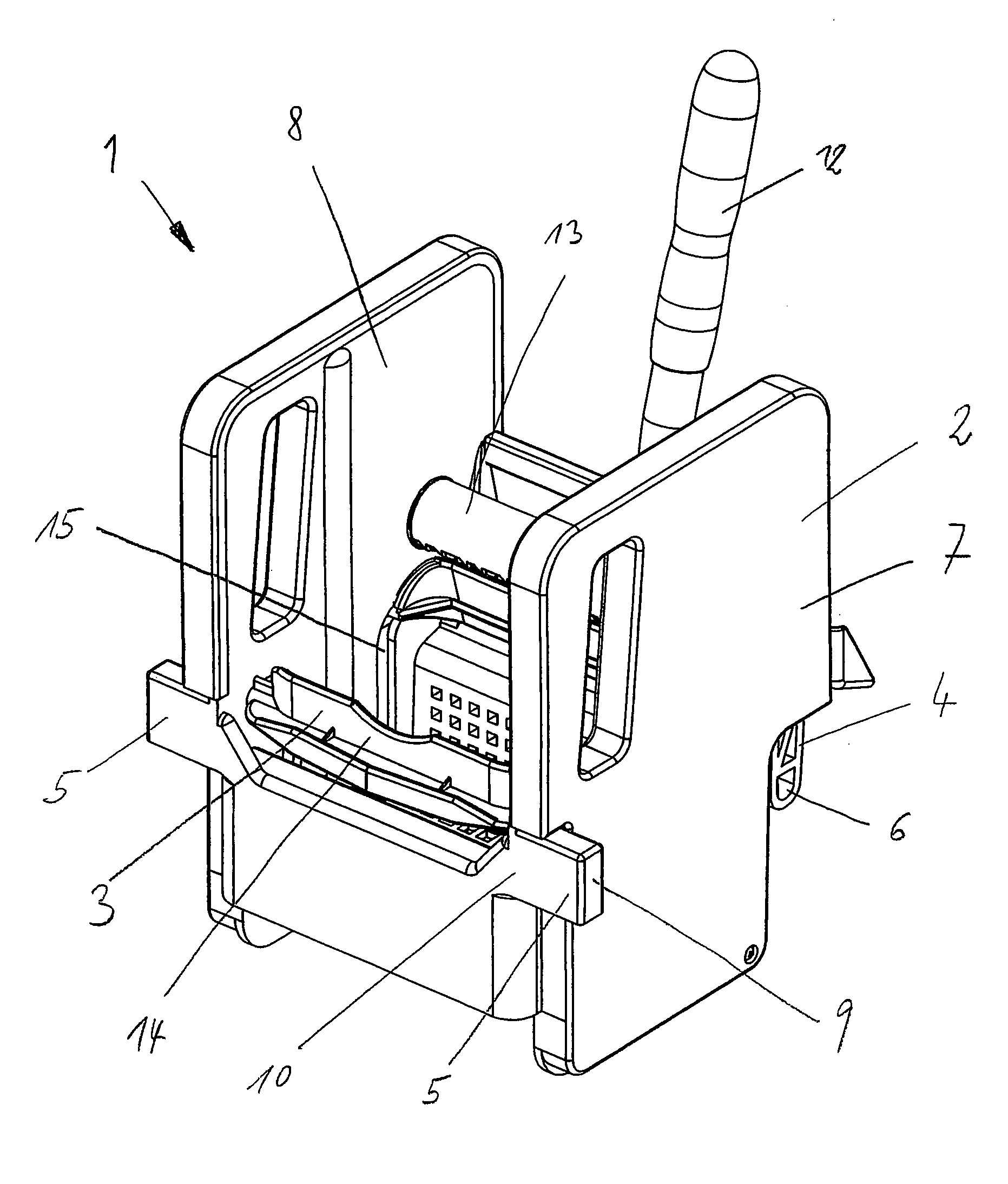
Figure 1 
Figure 2 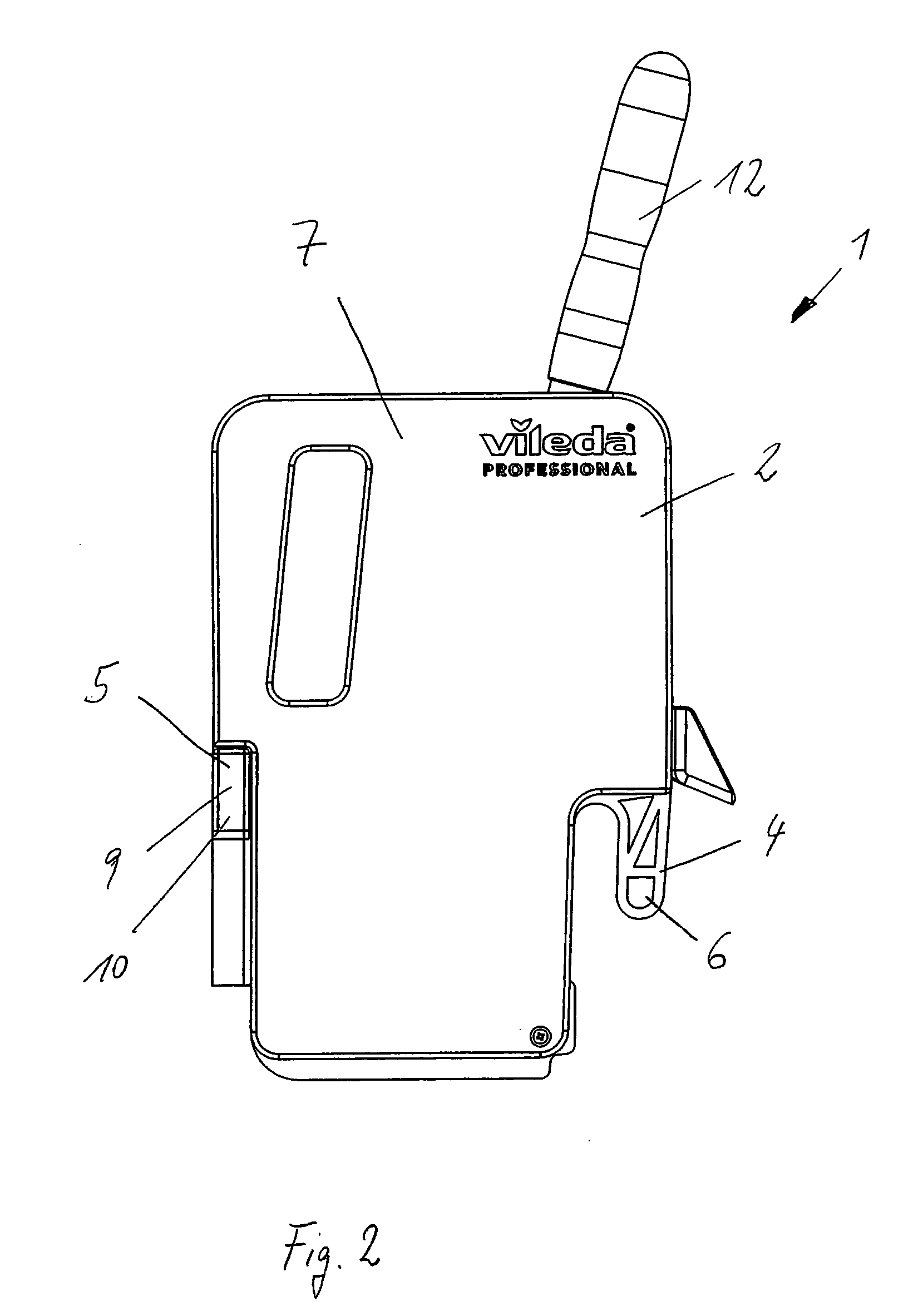
Figure 3
Abstract
Description
CROSS REFERENCE TO PRIOR APPLICATIONS
[0001] This application is a U.S. National Phase application under 35 U.S.C. §371 of International Application No. PCT / EP2009 / 002998, filed Apr. 24, 2009, which claims benefit to German Application No. DE 10 2008 022 364.6, filed May 6, 2008. The International Application was published in German on Nov. 12, 2009 as WO 2009 / 135594 under PCT Article 21 (2).FIELD
[0002] The invention relates to a mop press for wringing liquids out of a cleaning device, comprising a housing provided with a lever-actuated wringing device, said housing having a rear fastening mechanism.BACKGROUND
[0003] Such a mop press is known from German utility model DE 20 2006 015 209 U1. The mop press serves to squeeze liquids out of a cleaning device, for example, a flat pad or a wet mop. The wringing device comprises a lever that is operatively connected to pressing plates via a shaft. Depending on the configuration, these pressing plates can move in different directions and can als...
Examples
Embodiment Construction
[0021]FIG. 1 shows a mop press 1 for wringing liquids out of a cleaning device, comprising a housing 2 consisting essentially of two side panels 7, 8 at a distance from each other, between which a lever-actuated wringing device 3 is arranged. The wringing device 3 comprises a lever 12 that opens up into a shaft 13, whereby the shaft 13 is supported in the side panels 7, 8. Within the side panels 7, 8, there is a gear arrangement via which the shaft 13 is connected to the pressing bars 14. These pressing bars 14 are guided in a connecting link 15 and, as a result, follow a curved path. In the housing 2, there is a rear fastening mechanism 4 for affixing the mop press to a mop bucket 16 or to a cleaning trolley 17. The fastening mechanism 4 consists of a hook-shaped projection 6 that is affixed directly to the wringing device 3. For stiffening purposes, the projection 6 is provided with ribs. There is such a projection 6 on each side, in the immediate vicinity of the side panel 7, 8. ...