
Variable capacity type rotary compressor
Patent Information
- Authority / Receiving Office
- US · United States
- Current Assignee / Owner
- Publication Date
- 2011-05-26
- Estimated Expiration
- Not applicable · inactive patent
Smart Images
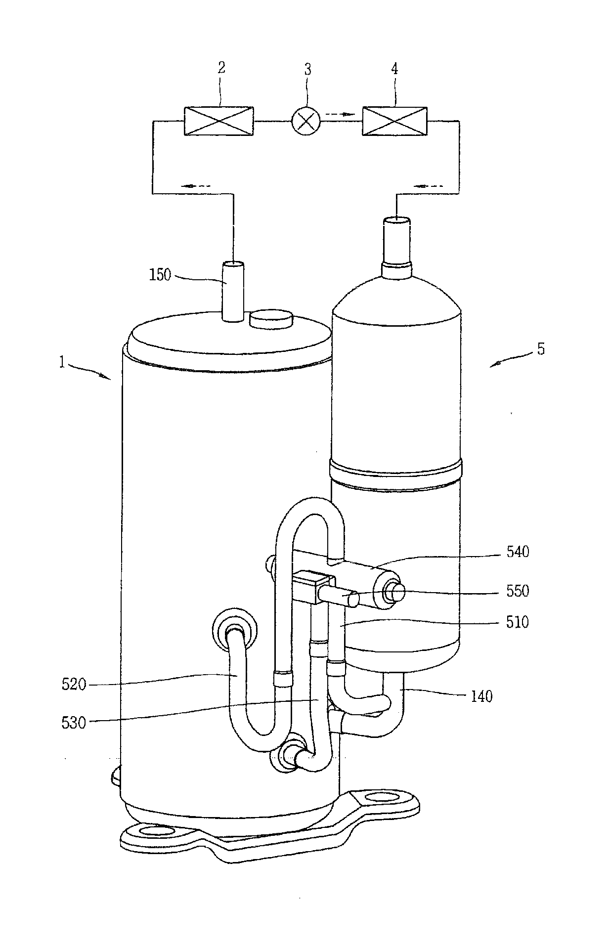
Figure 1 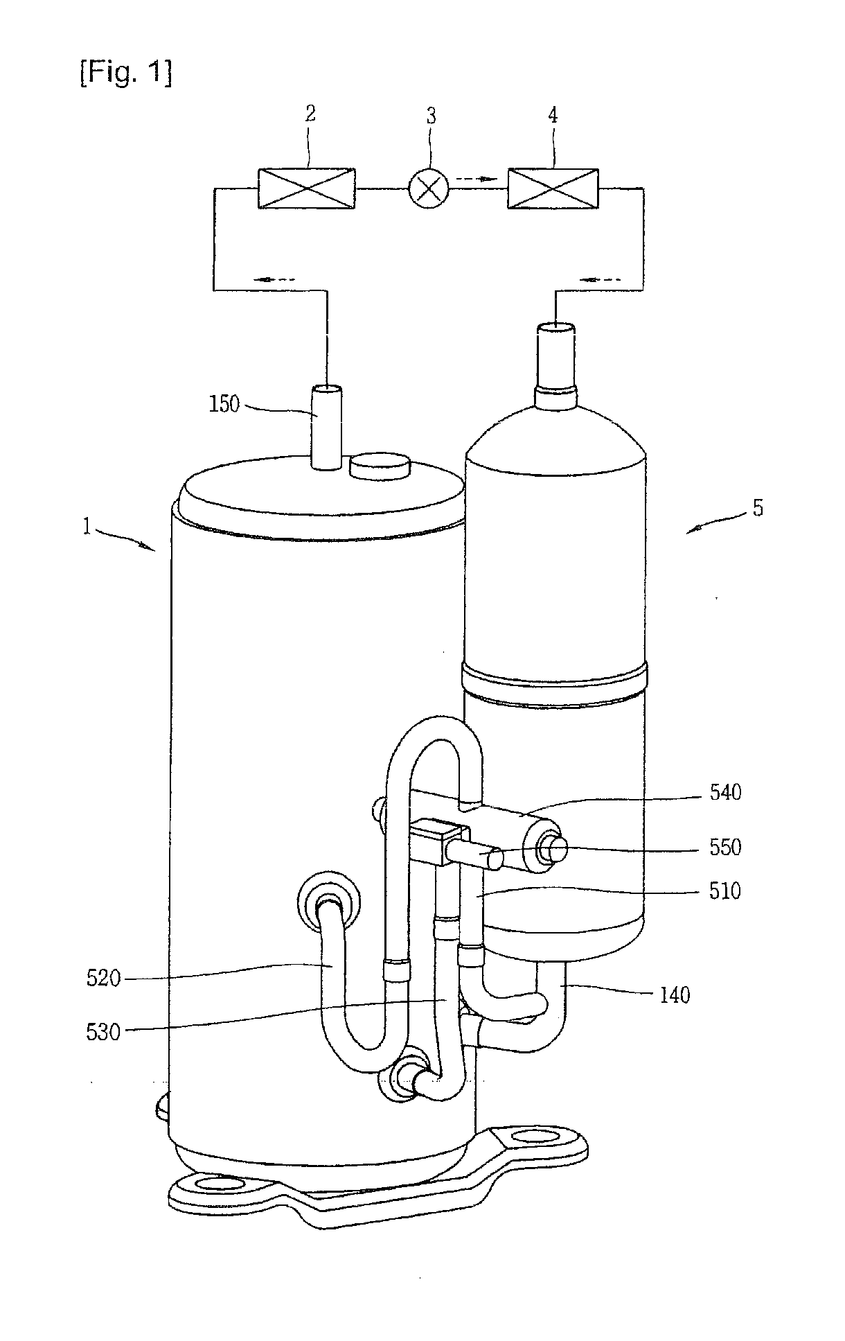
Figure 2 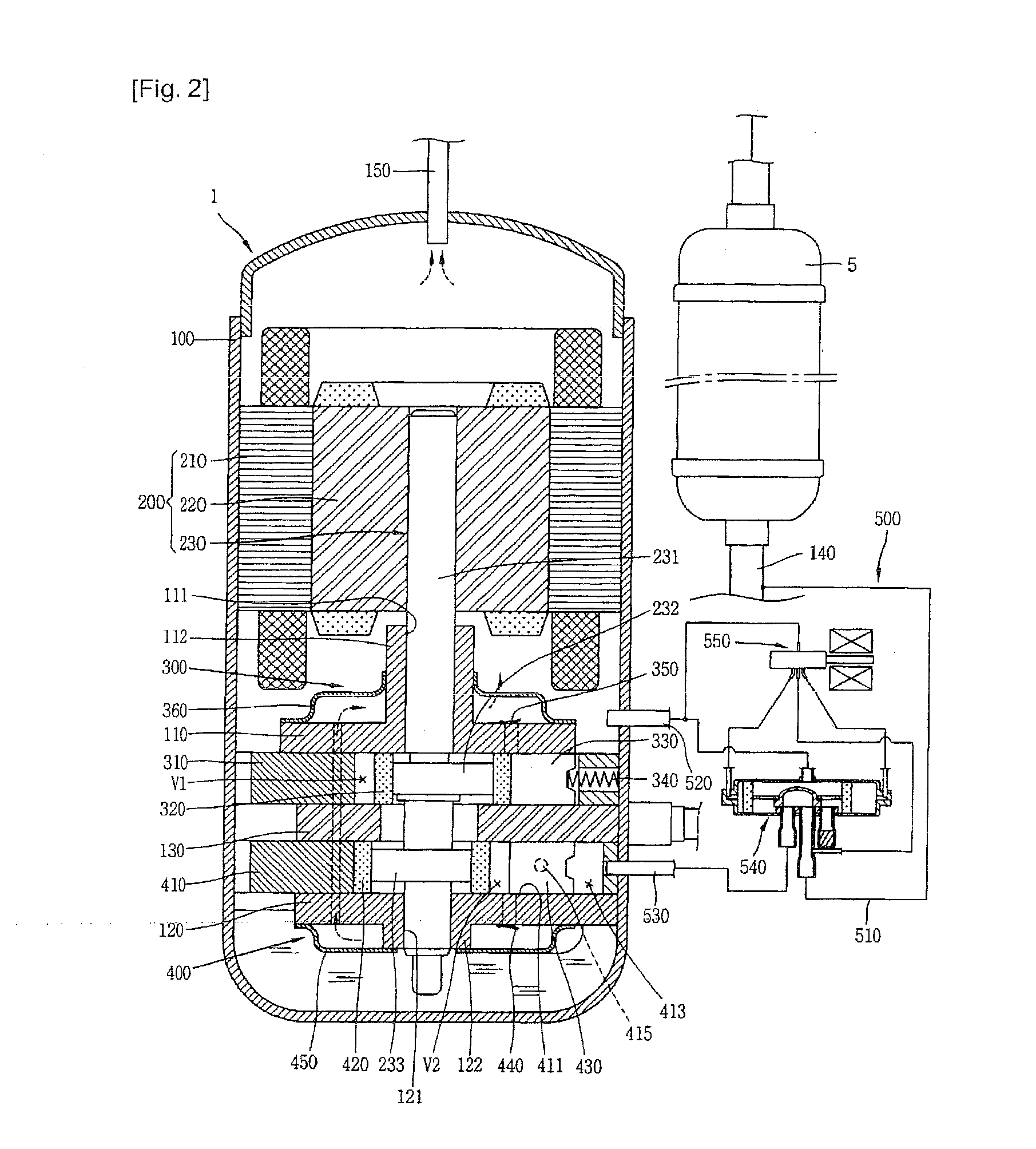
Figure 3
Abstract
Description
TECHNICAL FIELD
[0001] The present invention relates to a variable capacity type rotary compressor capable of being selectively operated in a saving mode or a power mode.BACKGROUND ART
[0002] In general, a refrigerant compressor is applied to a vapor compression type refrigerating cycle (hereinafter, referred to as ‘refrigerating cycle’), such as a refrigerator or an air conditioner. A constant-speed type compressor driven at constant speed and an inverter type compressor capable of controlling rotation speed have been introduced as the refrigerant compressor.
[0003] The refrigerant compressors are categorized as follows. A refrigerant compressor, in which a driving motor (typically, an electric motor) and a compression part operated by the driving motor are all installed in an inner space of a hermetic casing, is referred to as a hermetic type compressor, and a compressor of which the driving motor is separately installed outside the casing is referred to as an open type compressor. Home...
Examples
Embodiment Construction
[0040]Description will now be given in detail of a variable capacity type rotary compressor in accordance with one embodiment of the present invention, with reference to the accompanying drawings.
[0041]As shown in FIG. 1, a variable capacity type rotary compressor 1 according to the present invention may be configured such that a suction side thereof is connected to an outlet side of an evaporator 4 and simultaneously a discharge side thereof is connected to an inlet side of a condenser 2 so as to form a part of a closed loop refrigerating cycle including the condenser 2, an expansion apparatus 3 and the evaporator 4. An accumulator 5 for separating a refrigerant carried from the evaporator 4 to the compressor 1 into a gaseous refrigerant and a liquid refrigerant may be connected between the discharge side of the evaporator 4 and the inlet side of the compressor 1.
[0042]The compressor 1, as shown in FIG. 1, may include a motor part 200 installed at an upper side of an inner space of...