
Method for identifying a sequence of input signals
Patent Information
- Authority / Receiving Office
- US · United States
- Current Assignee / Owner
- Publication Date
- 2011-11-24
- Estimated Expiration
- Not applicable · inactive patent
Smart Images
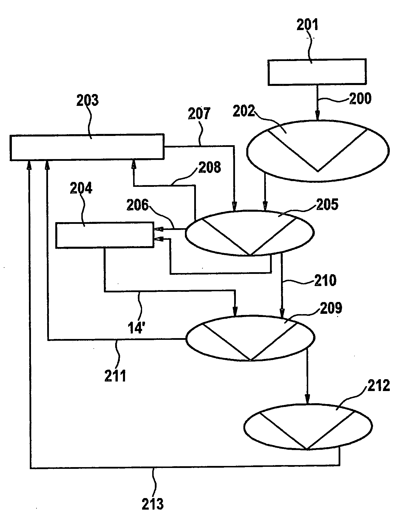
Figure 1 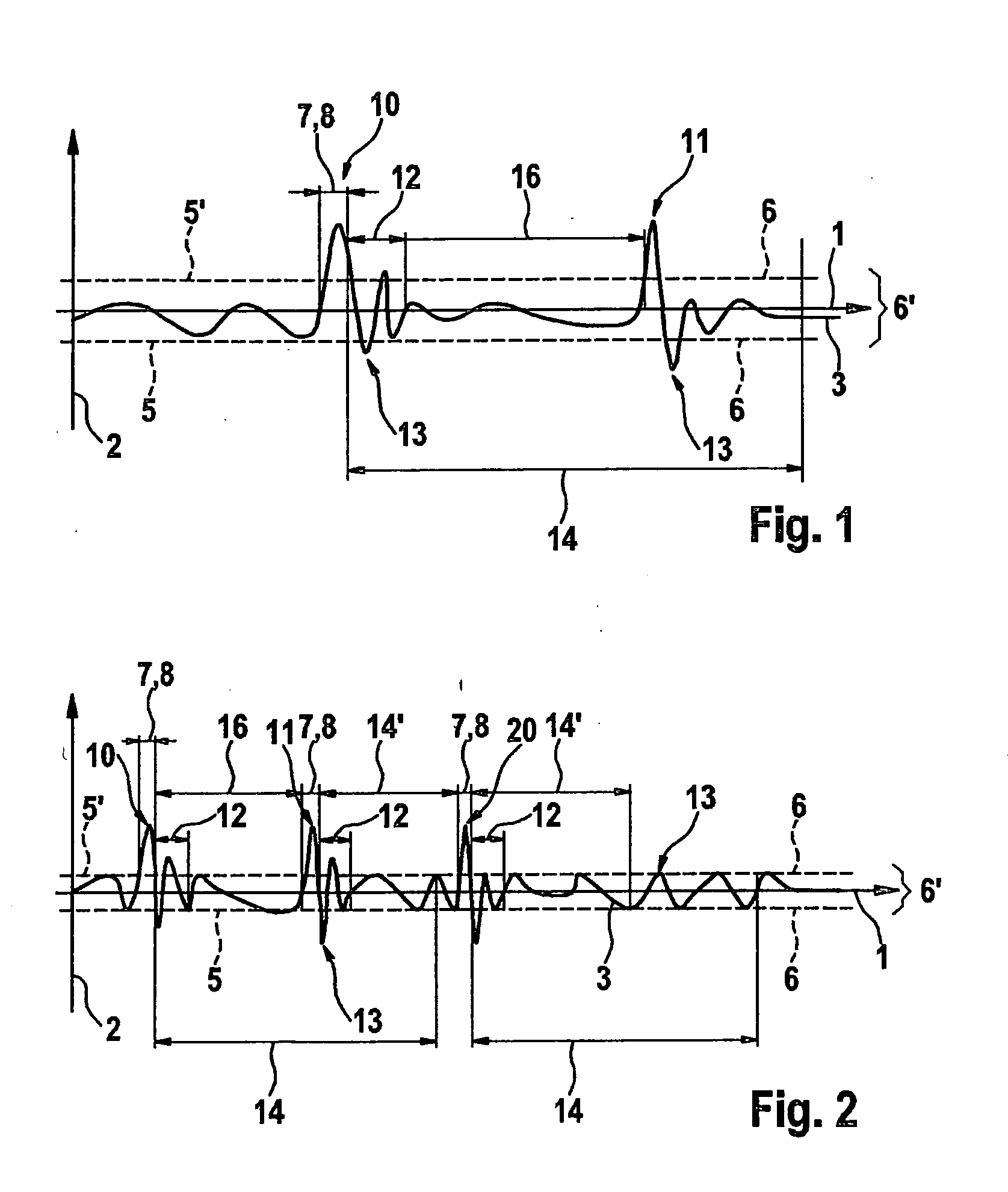
Figure 2 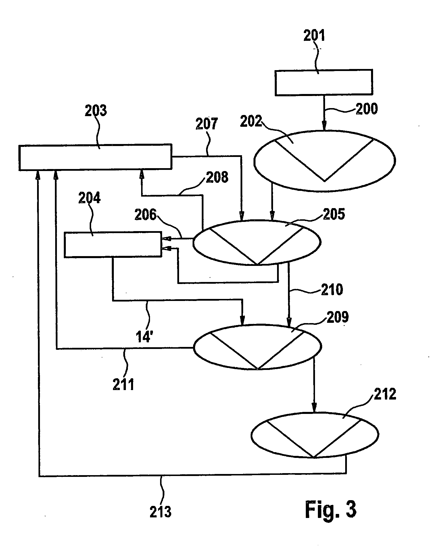
Figure 3
Abstract
Description
[0001] The present invention is directed to a method for identifying a sequence of input signals according to the definition of the species of Claim 1.
[0002] Such methods are generally known. For example, document DE 10 2004 001 226 A1 describes a method for identifying a double click, a first touch being detected using a key device in a first step, a second touch being detected using the key device in a second step, and a double-click signal being output in a third step if the sum of the durations of the first touch, the second touch, and the time interval between the first and second touches is less than a reference time. Thus, after the first touch, an identifying unit checks whether a second touch occurs within the reference time. In the case where no second touch occurs, the system waits for the entire reference time to elapse before a double-click signal may be ruled out. The disadvantage of this method is that the reference time is a fixed constant, so tha...
Examples
Embodiment Construction
[0018]FIG. 1 shows a schematic view of a method according to a first specific embodiment of the present invention, a diagram having an abscissa 1 and an ordinate 2 being shown in FIG. 1; time is plotted on abscissa 1 and the amplitude is plotted on ordinate 2. Furthermore, in the diagram the amplitude of a signal 3 is plotted against time, signal 3 including, for example, an acceleration signal of an acceleration sensor (not illustrated), the acceleration signal including in particular the variation of an acceleration as a function of time. In the diagram, a signal threshold value 6, which has a constant value and defines a subthreshold range 6′ around abscissa 1, is shown in the form of two dashed lines 5, 5′. Signal 3 is identified only when the absolute value of signal 3 at a certain point in time is greater than the absolute value of signal threshold value 6 and consequently signal 3 is outside subthreshold range 6′. In addition, signal 3 must be outside subthreshold range 6′ fo...