
Modular clamp station with variable pitch
a module-type clamping and variable-pitch technology, which is applied in the direction of auxillary shaping apparatus, ceramic shaping apparatus, manufacturing tools, etc., can solve the problems of heavy machines, undesirable deformation of the frame by the clamping force, and high cost of blow molding apparatuses described abov
Patent Information
- Authority / Receiving Office
- US · United States
- Patent Type
- Applications(United States)
- Current Assignee / Owner
- Publication Date
- 2012-09-13
Smart Images
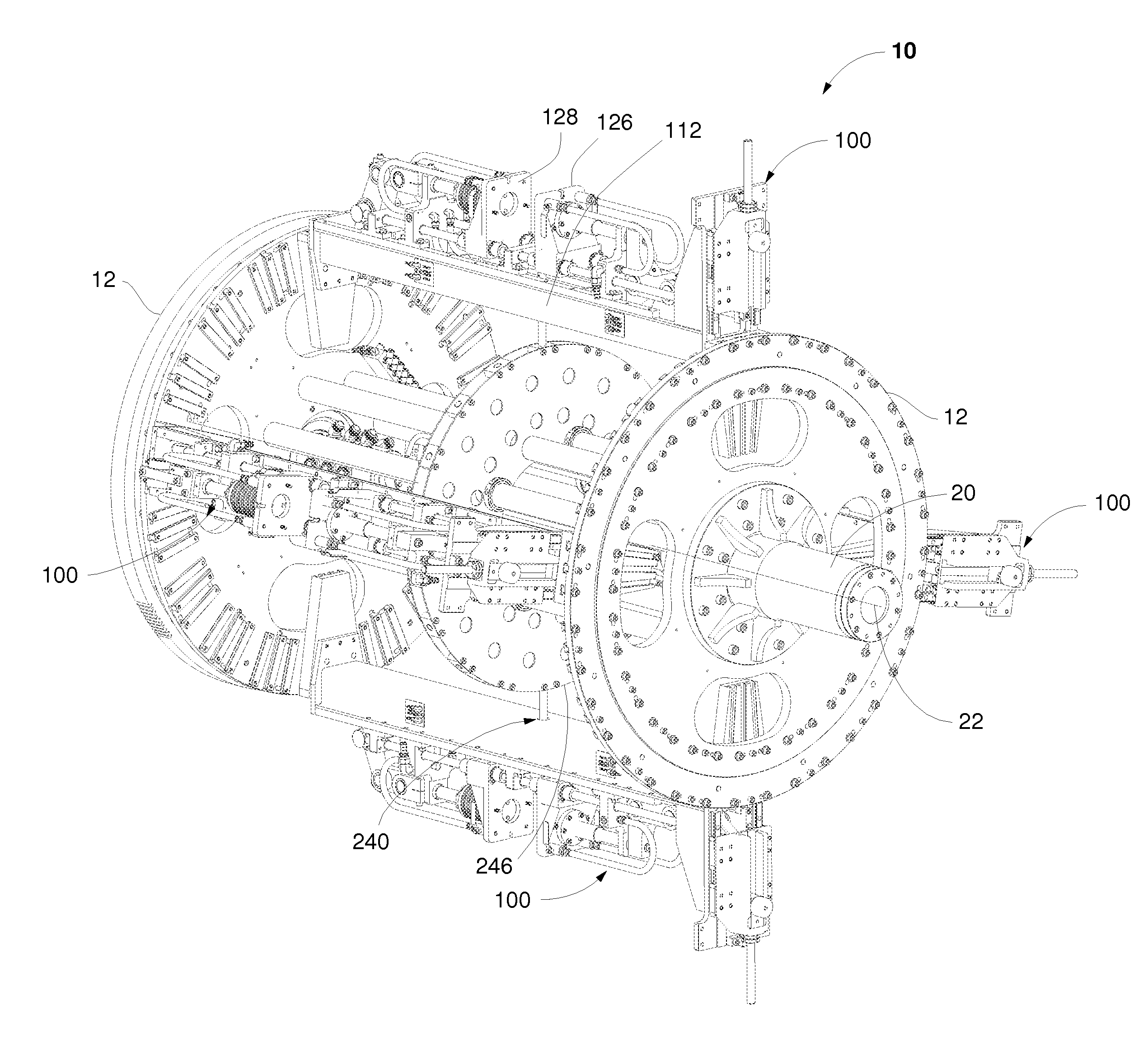
Figure 1 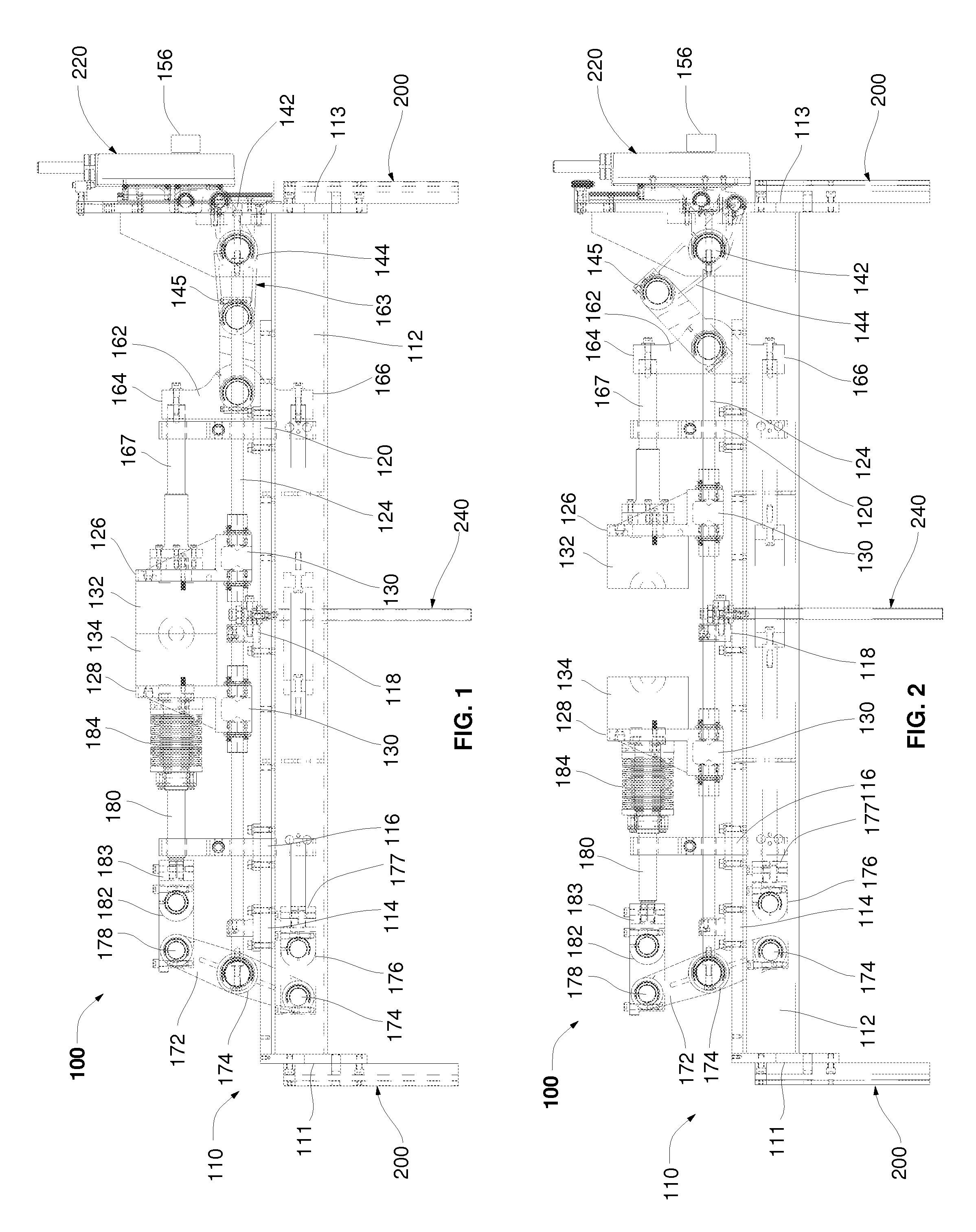
Figure 2 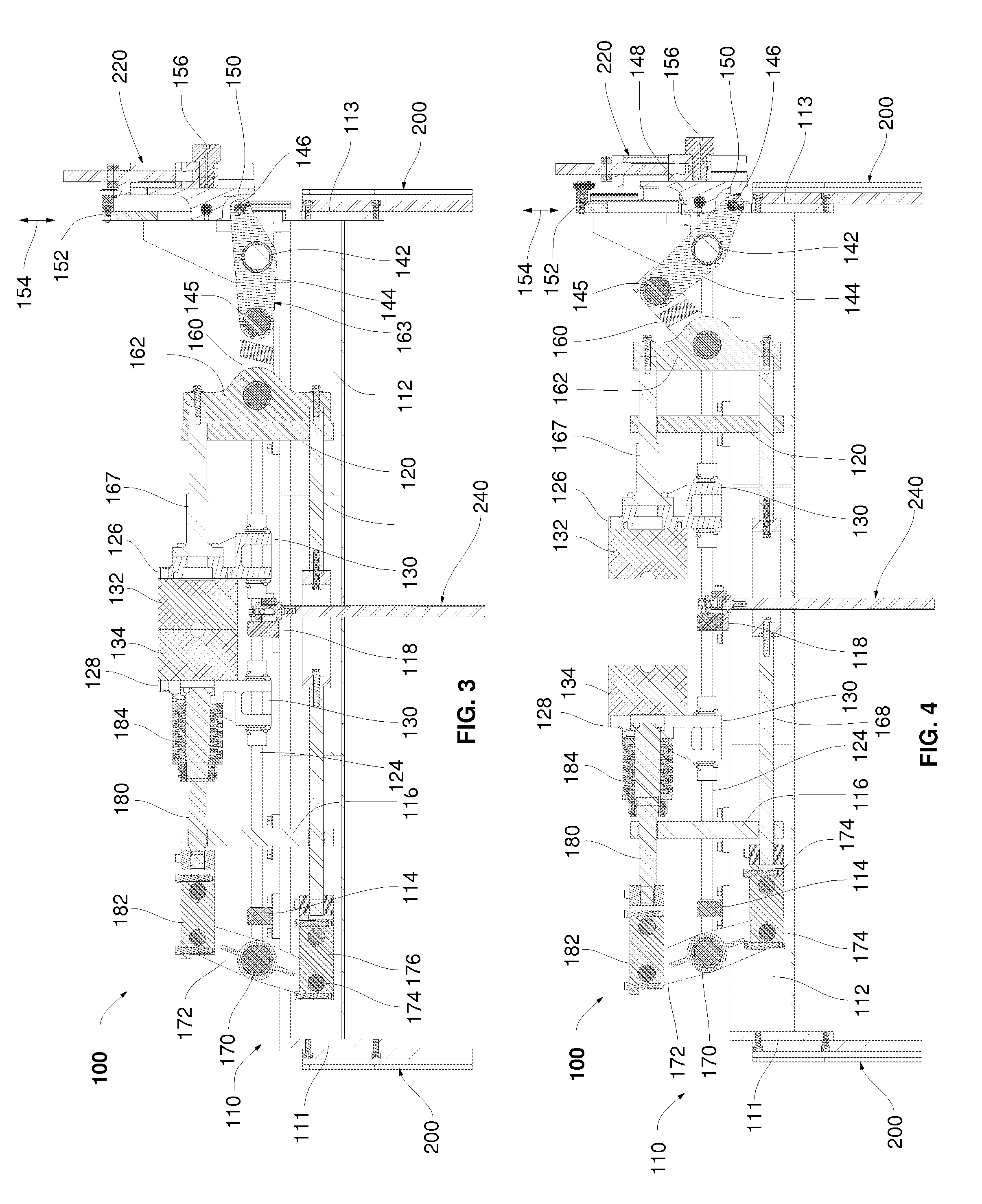
Figure 3
Abstract
Description
CROSS-REFERENCES TO RELATED APPLICATIONS
[0001] This application is a Continuation-in-Part application under 35 U.S.C. §121 of U.S. patent application Ser. No. 12 / 898,824 filed Oct. 2, 2010, which is hereby incorporated by reference in its entirety.FIELD OF THE INVENTION
[0002] The invention relates generally to an extrusion molding apparatus. Specifically, the present invention relates to modular mold clamping assemblies with a variable pitch for use with the molding apparatus.BACKGROUND OF THE INVENTION
[0003] Conventional rotary extrusion blow molding apparatuses typically have a structural frame mounted on a rotating shaft. The structural frame has a plurality of molds mounted thereon and is known in the industry as a wheel. As the wheel is rotated, the plurality of molds is rotated past an extrusion die extruding a continuous parison. Each mold typically includes two mold halves, each comprising a mold cavity half therein, such that when the mold halves are closed, the mold defines a...
Examples
Embodiment Construction
[0031]Referring to FIGS. 9-11, a wheel 10 of a blow molding machine is illustrated. However, the invention is not limited to a blow molding machine, as other molding machines can be used without departing from the scope of the invention. The blow molding machine has a base (not shown) upon which the wheel 10 is rotatably supported. An extruder (not shown) is positioned adjacent the wheel 10. The wheel 10 has two essentially parallel radially extending plates or turntables 12 which carry a plurality of modular mold clamp assemblies 100, each having an inner cavity (not depicted) to receive a parison from the extruder. The wheel 10 is mounted on shafts 20, 21 which have a drive which rotates the wheel 10 and modular mold clamp assemblies 100 about a rotational axis or center 22 of the wheel 10 and the shafts 20, 21 to direct each mold secured by the modular mold clamp assemblies 100 between extrusion, blow molding, cooling and ejection stations, as is known in the art. In the depicted...