
Conductive adhesive mixture, fluorescent screen anode plate and the manufacturing methods thereof
Patent Information
- Authority / Receiving Office
- US · United States
- Current Assignee / Owner
- Publication Date
- 2013-03-28
- Estimated Expiration
- Not applicable · inactive patent
Smart Images
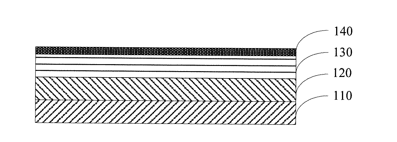
Figure 1 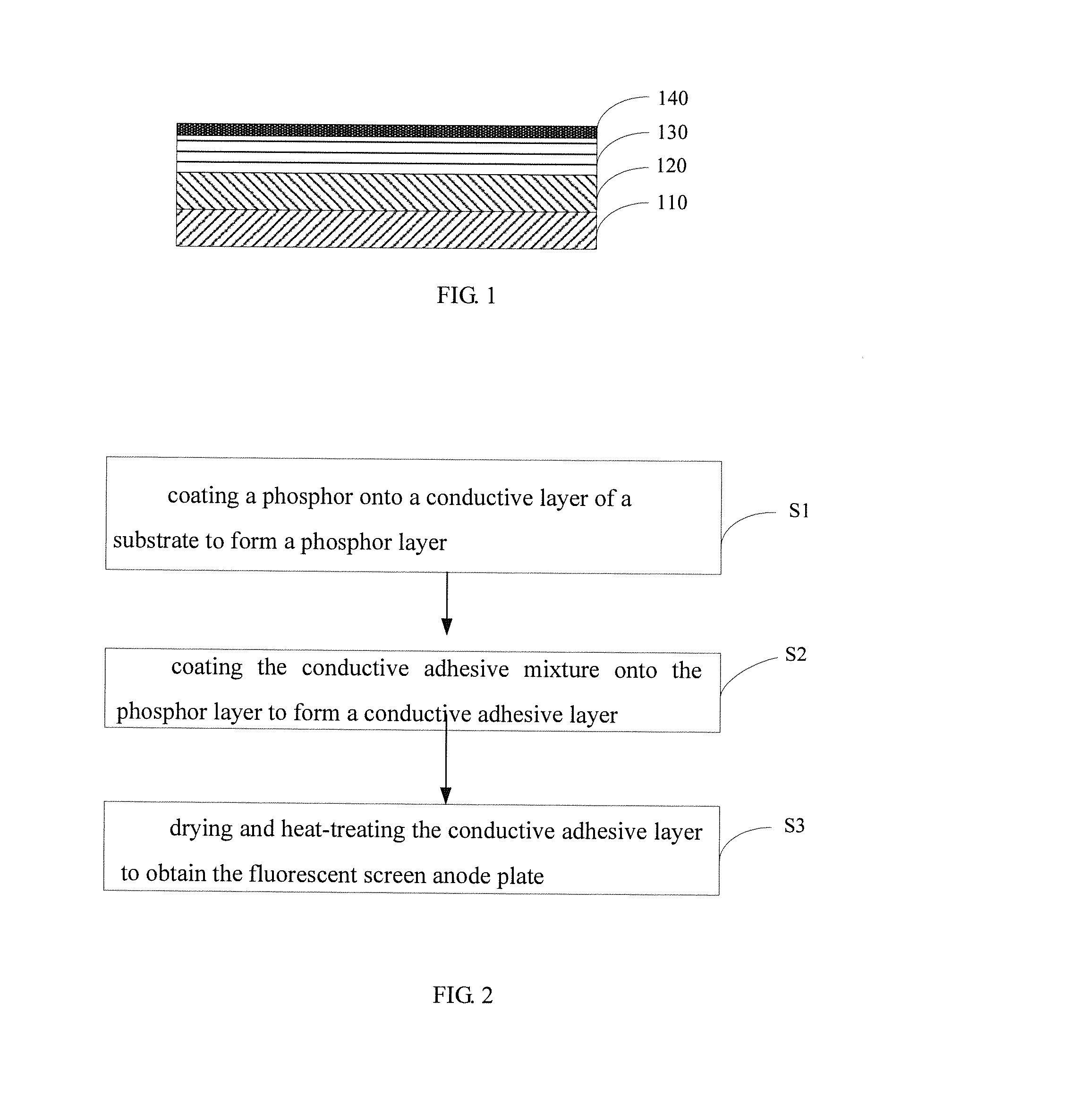
Figure 2
Abstract
Description
FIELD OF THE INVENTION
[0001] The present invention relates to vacuum microelectronics technologies, and especially to a conductive adhesive mixture, a fluorescent screen anode plate and manufacturing methods thereof.BACKGROUND OF THE INVENTION
[0002] The cathodoluminescence device, particularly the field emission light source, has such advantages as energy saving, environmental protection, fast starting, being thin and light, as well as strong environmental adaptability. In the era of vigorously advocating energy saving and environmental protection, it has become an important research topic in various countries as an environmental lighting source and has huge development potential.
[0003] The field emission light can be applied to the lighting source and information terminal display device. The structure of the field emission luminous device is mainly composed of a cathode electron source and an anode luminous screen. The anode luminous screen is composed of a glass substrate, a conducti...
Examples
example 1
[0036]Preparation of the conductive adhesive mixture: 28 g of SnCl4, 70 g of potassium silicate, 700 ml of ionized water, and 2 g of Sn nanoparticles were mixed together, and then the mixture was subjected to ultrasonic waves for 30 minutes to produce the conductive adhesive mixture.
[0037]An ITO glass was cut according to a predetermined size, and then washed with acetone, alcohol and deionized water, respectively. After the ITO glass was dried, a yttrium terbium silicate green phosphor was deposited onto an ITO surface of the ITO glass to form a phosphor layer, and then the ITO glass was heat-treated at 450° C. for 30 minutes. Finally, a conductive adhesive was coated onto the surface of the phosphor layer by the spincoating process and dried at a low temperature of 45° C., and the conductive adhesive was heat treated at 120° C. for 5 hours to obtain the fluorescent screen anode plate. The conductive adhesive layer therein had a thickness of about 0.1
example 2
[0038]Preparation of the conductive adhesive mixture: 4.5 g of InCl3 solution, 95 g of sodium silicate, 600 ml of ionized water, and 0.5 g of In nanoparticles were mixed together, and then the mixture was subjected to ultrasonic waves for 30 minutes to produce the conductive adhesive mixture.
[0039]An ITO glass was cut according to a predetermined size, and then washed with acetone, alcohol and deionized water, respectively. After the ITO glass is dried, an yttrium europium oxide red phosphor was deposited onto an ITO surface of the ITO glass to form a phosphor layer, and then the ITO glass was heat-treated at 450° C. for 1 hour. Finally, a conductive adhesive was coated onto the surface of the phosphor layer by the infiltration process and dried at a low temperature of 50° C., and the conductive adhesive was heat treated at 150° C. for 2 hours to obtain the fluorescent screen anode plate. The conductive adhesive layer therein had a thickness of about 2 μm.
example 3
[0040]Preparation of the conductive adhesive mixture: 28 g of SbCl3, 72 g of poly(silicon dioxide), and 350 ml of deionized water were mixed together, and then the mixture was subjected to ultrasonic waves for 30 minutes to produce the conductive adhesive mixture.
[0041]An ITO glass was cut according to a predetermined size, and then washed with acetone, alcohol and deionized water, respectively. After the ITO glass was dried, an yttrium europium oxide red phosphor was deposited onto an ITO surface of the ITO glass to form a phosphor layer, and then the ITO glass was heat-treated at 450° C. for 2 hours. Finally, a conductive adhesive was coated onto the surface of the phosphor layer by the spincoating process and dried at a low temperature of 50° C., and the conductive adhesive was heat treated at 130° C. for 5 hours to obtain the fluorescent screen anode plate. The conductive adhesive layer therein had a thickness of about 1 μm.