
Multi-axle joint shifting loading apparatus for processing center and detection method for static stiffness distribution
a technology of static stiffness distribution and loading apparatus, which is applied in the direction of structural/machine measurement, instruments, manufacturing tools, etc., can solve the problems of cutting load not being fully simulated at the main axle side, and the inability to detect static stiffness distribution
Patent Information
- Authority / Receiving Office
- US · United States
- Patent Type
- Applications(United States)
- Current Assignee / Owner
- Publication Date
- 2013-05-09
Smart Images
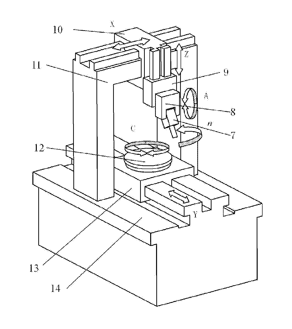
Figure 1 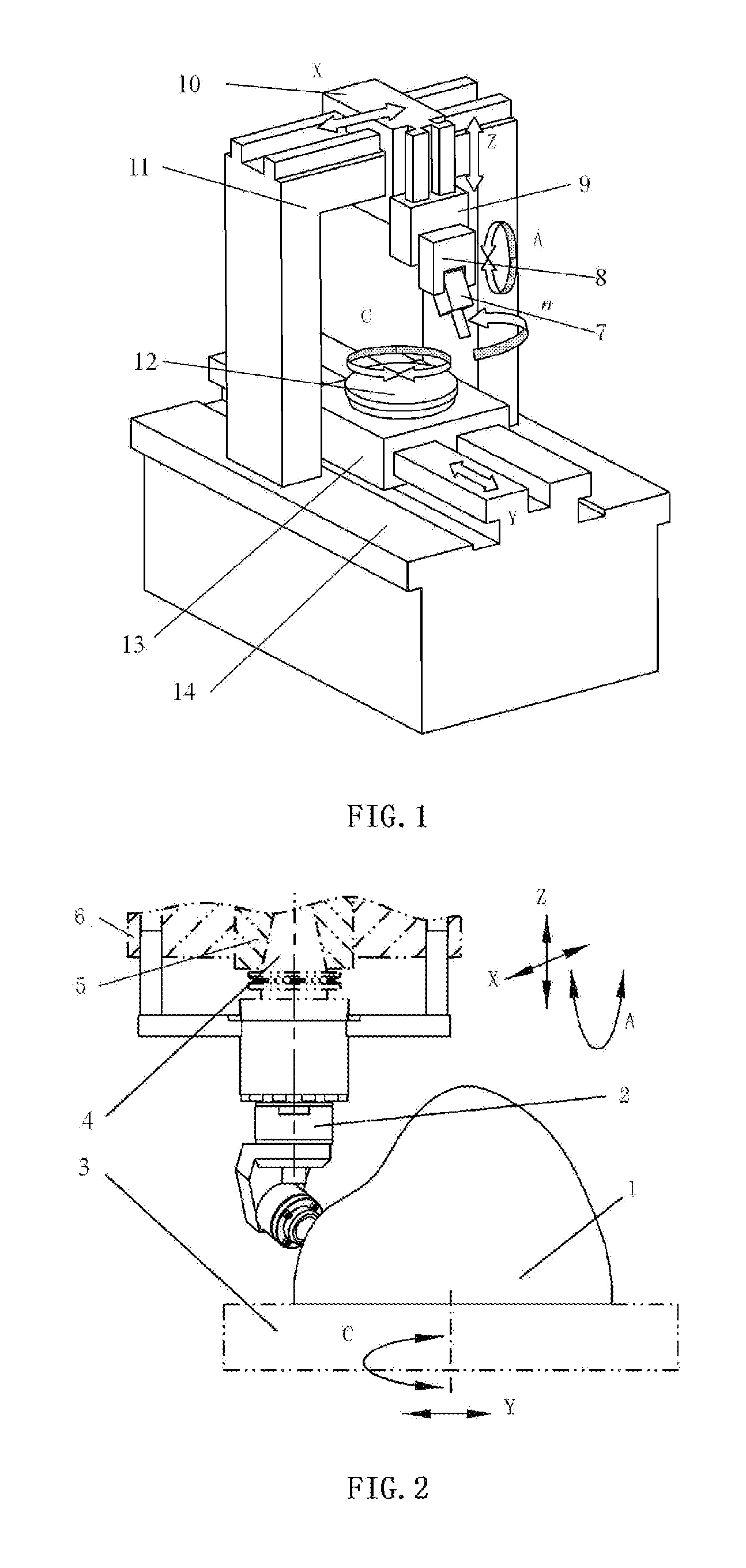
Figure 2 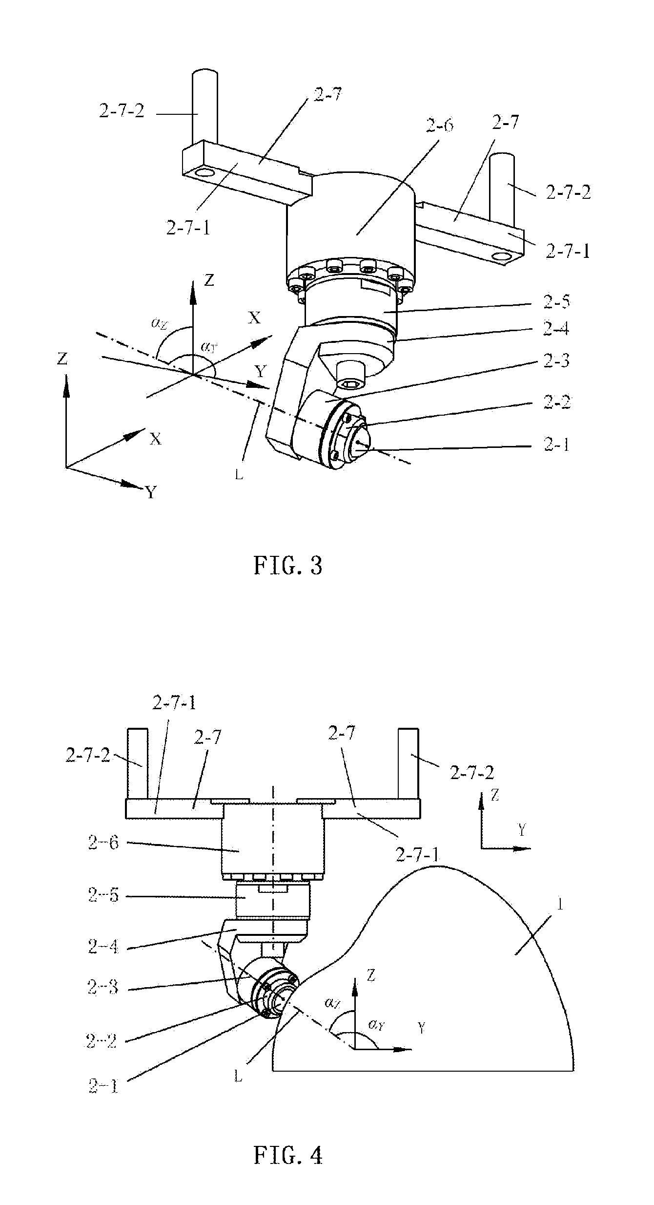
Figure 3
Abstract
Description
TECHNICAL FIELD
[0001] The present invention belongs to a detection technology for simulating static stiffness of numerical controlling machine tools under loads at different positions in a working space, and more particularly relates to a multi-axle joint shifting loading apparatus for a processing center and a detection method for a static stiffness distribution.BACKGROUND ART
[0002] In a working space of a machine tool, the magnitude of loads (including force and moment) and loading positions of members of the machine tool vary as the position of the machining point varies, so that a static stiffness distribution of the machine tool changes. The change in static stiffness at different machining positions may be described by a stiffness distribution. The magnitude of the static stiffness and the static stiffness distribution influence the machining precision directly (especially the stiffness distribution influences the shape precision of the machining surface directly), and influence...
Examples
embodiment 1
[0030]When the shifting loading apparatus according to the present invention is used in a 5-axle joint upright processing center or a horizontal processing center, the method for detecting the processing center static stiffness distribution is as follows: as shown in FIGS. 2 and 4, firstly the connection component A 2-6 of the load-exerting component 2 is fixedly connecting with the tool shank 4, wherein the tool shank 4 is tensioned in the taper hole in the main axle 5, and the connection component B 2-7 disposed on the connection component A 2-6 is connected with the main axle housing 6 through the vertical bar 2-7-2; the load-receiving test piece 1 is mounted on the worktable 3; a displacement sensor is mounted, which may be installed in plural, for example, on the main axle 5, the main axle housing 6 and the worktable 3; then the load-exerting component 2 and the load-receiving test piece 1 are moved to a preset first loading position through a joint movement of Z axle, Y axle, ...
embodiment 2
[0031]When the shifting loading apparatus according to the present invention is used in a 5-axle joint turning-milling composite processing center, the method differs from the first embodiment in that a position function is utilized when the main axle performs a turning cutting, and thus the connection component B 2-7 is not required, wherein the multi-axle joint shifting loading apparatus is illustrated in FIG. 5, as long as the connection component A 2-6 and the tool shank 4 are fixedly connected, the tool shank 4 is tensioned in a taper hole in the main axle 5, and the load-receiving test piece 1 is mounted on the worktable 3, the detection method can be performed. In this case, the method for detecting the static stiffness distribution of the processing center is the same as that of the first embodiment, that is to say, the method also change the loading position through a joint movement of Z axle, Y axle, X axle, C axle and A axle, the detailed description of which is omitted h...
embodiment 3
[0032]When the shifting loading apparatus according to the present invention is used in a 4-axle joint processing center having X axle, Y axle, Z axle and C axle (that is, the processing center shown in FIG. 1 has no A axle), the load exerting component 2 is connected to the processing center in the same manner of the first embodiment with a difference that the loading position is changed through a joint movement of X axle, Y axle, Z axle and C axle. The shape of the load-receiving surface of the load-receiving test piece 1 can be designed in a rather simple manner.
[0033]Among the axles, a slewing axle, an axis of which is parallel with X axle is called as A axle; and a slewing axle, an axis of which is parallel with Y axle is called as B axle, and a slewing axle, an axis of which is parallel with Z axle is called as C axle.